.png?v=1611050572224)
.png?v=1611050431932)
.png?v=1611050548824)
.png?v=1611050119333)
.png?v=1611050465355)
.png?v=1611050452767)
.png?v=1611050558000)
.png?v=1611738745088)
.png?v=1611050528853)
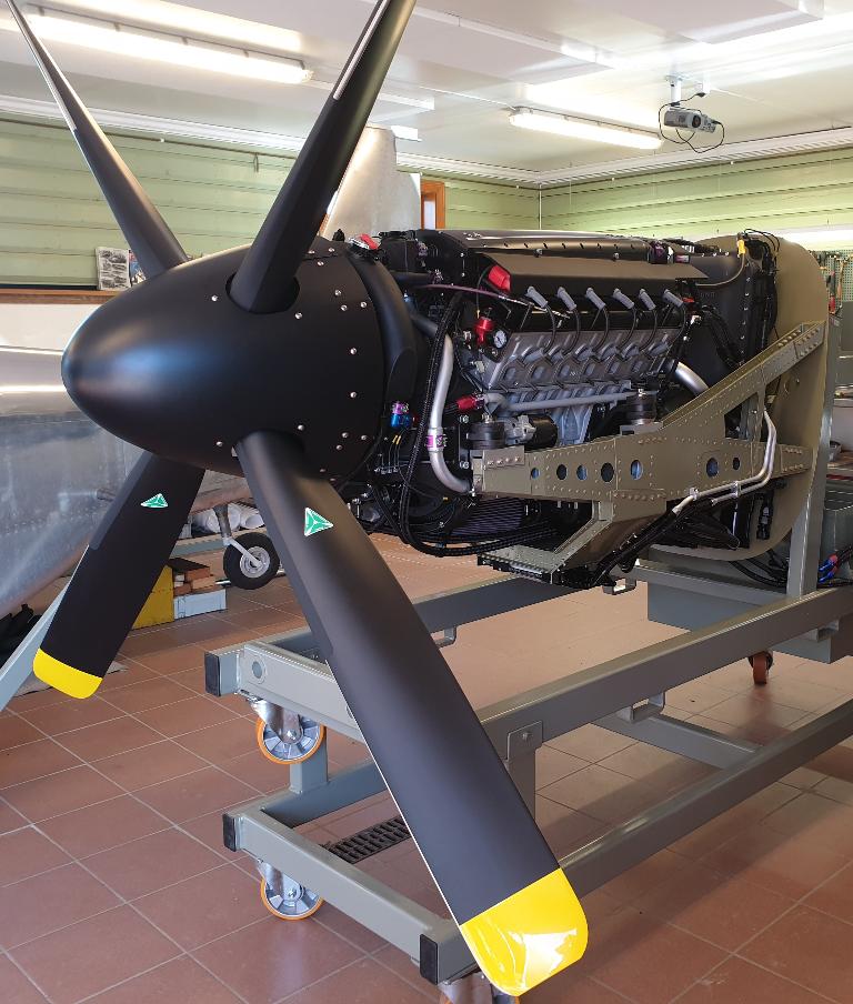
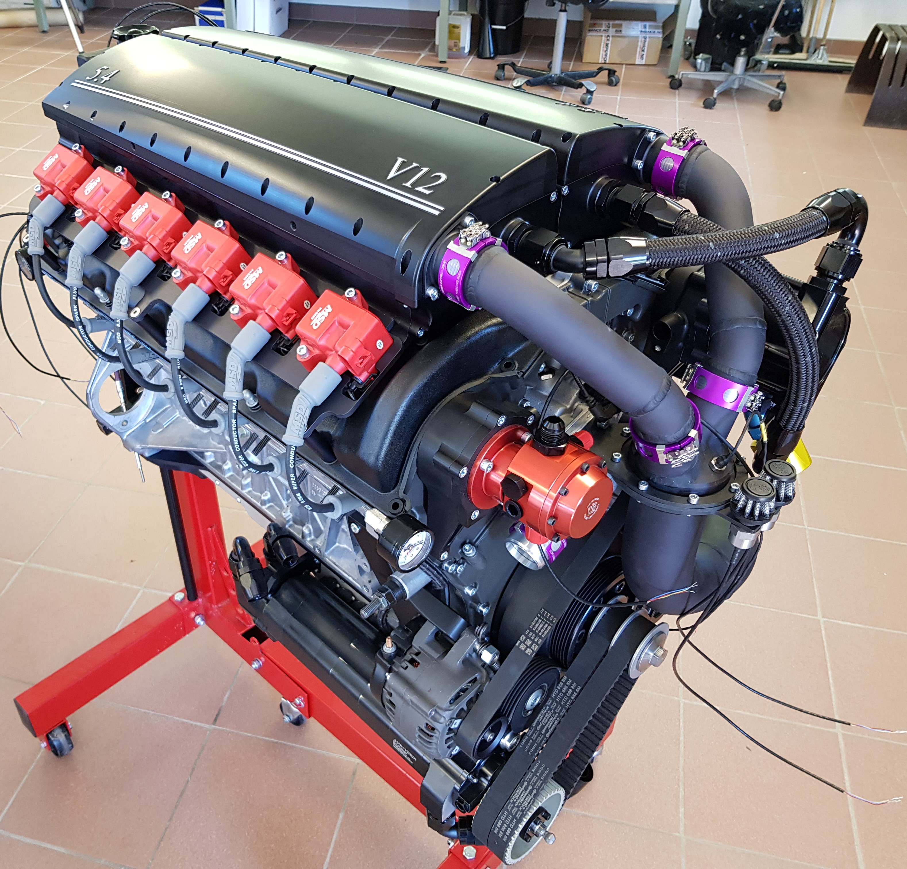
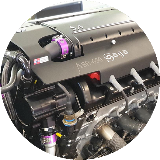
The ASE-650 SAGA
The name of the powerplant, ASE-650 SAGA refers to us, our company Aerosport Engineering AS, to an indication of power output, and to the attempt to continue a history of Norwegian craftmanship.
Important Aircraft Engine Properties
As an airman, you will have to agree that reliability and safety are of major importance and on top of your priority list. Next on the list will be that the powerplant is light, powerful, rigid and relatively fuel efficient! There is an obvious downside to this! Important aircraft engine qualities merged into low volum production units like the ASE-650 Saga, does not come free of charge! This is a typical example of a CEO's wet dream, and quite obviously, a result of poor market research. So, because of that, we have a small quantity of these units waiting for the right experimental aircraft builders to put in an order! This is like buying a Rolls-Royce, you just order, and never ask the price!
The problematic convertion
Ok, lets face it, we know that the discussion is going on world wide; one can not convert an automobile engine into an Aero engine. Period! Why is that? Where does that perception come from? What makes a car engine unsutiable for an aircraft? Are there any underlying facts for these statements, or are they just old "beliefs" and assumptions? Could it be that this general perception is based on a knowledge that til now gives room for some uncertainty with regards to whether or not an automobile engine is suitable as an aircraft powerplant. Maybe this has discuraged anyone looking closer at the possibility to use a CAR engine in an aircraft.
From the Bayerische Motoren Werke to the Norwegian ASE-650 Saga
We would appreciate it, if you could give us a moment to let us explain the various reasons that Aerosport Engineering chooses to pursue this rather complicated task. In that regard, we would like to use our particular choise of engine as an example. We think it will be easier to grasp the consept, and to understand what a convertion is actually about, after you have seen the modifications we have made to the base engine. The modifications are substantial, with the primary goal to make it a safe aircraft power plant. Safety is the main focus of this discussion! The BMW M73-B54 platform, as in this example, has some OEM qualities that we can benefit from, but also some features that needs to be adressed. Please be our guests to learn more about our ASE-650 Saga further down on this page.
Chosing the Base Engine
If you’re not planning to construct an engine from scratch, which is first of all, quite difficult, but also a time consuming and extremely expensive task, you will need a base engine to start with, using it as a platform for your own ideas. Choosing the right platform is absolutely crucial for a successful end result. V12 engines are a limited resource on the existing market, and the choice amongst them narrows down quite fast.
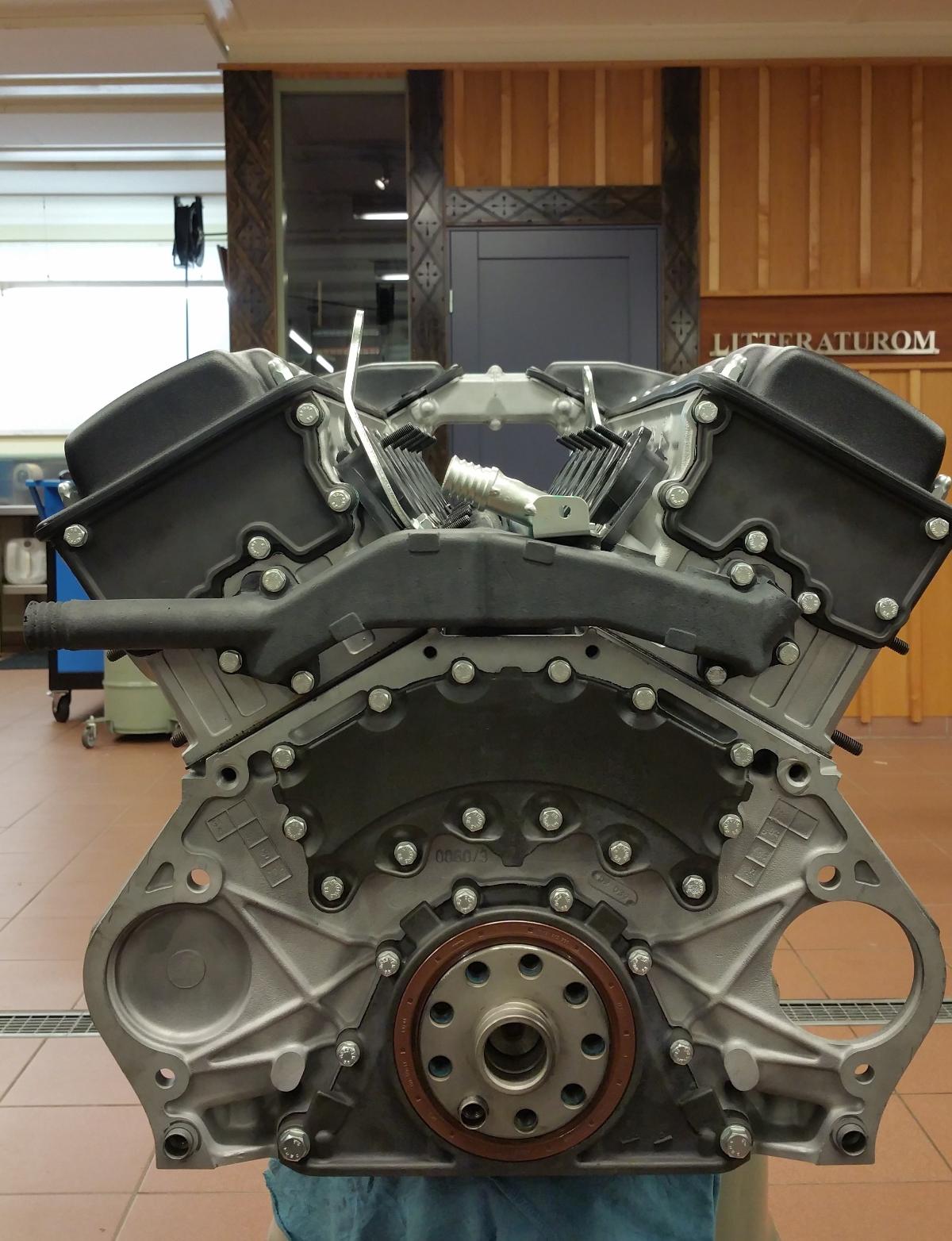
The engine we chose as our base, is manufactured by BMW with factory code M73-B54. This was manufactured during a period of 12 years, from 1991 to 2003. It is an all aluminum 60 degree 5,4 lt (330 Cid) V12, basically used in the BMW 750, (E38 and E31 body) The engine does not incorporate separate steel cylinder liners which implies that the cylinders consist of the same aluminum and silicone compound as that of the rest of the engine block. This casting technology is known as AluSil.
Nicasil cylinders
We have treated all our engine blocks/cylinder liners with a thin layer of nikasil in order to increase cylinder wall durability. An aircraft engine works under relatively high load during most operation, and we want to make sure that the engine is preapared to meet the extra demands from such operation.
Valvetrain
The engine is equipped with single overhead camshafts, operating one intake, and one exhaust valve pr. cylinder. The camshaft and lifters are of the roller type from the factory. We deliberately chose these engines because they do not use Vanos / variable camshaft timing, nor Valvetronic / variable valve lift.
Piston Cooling nozzles
Another important factor built into the engine by the factory, is the piston oil cooling nozzles. They are fitted directly into the main bearing support area of the block which accesses the main oil pressure supply. The steady oil stream from the nozzles continuously cools the underside of the piston. This is a very important safety factor on engines undergoing continuous high loads.
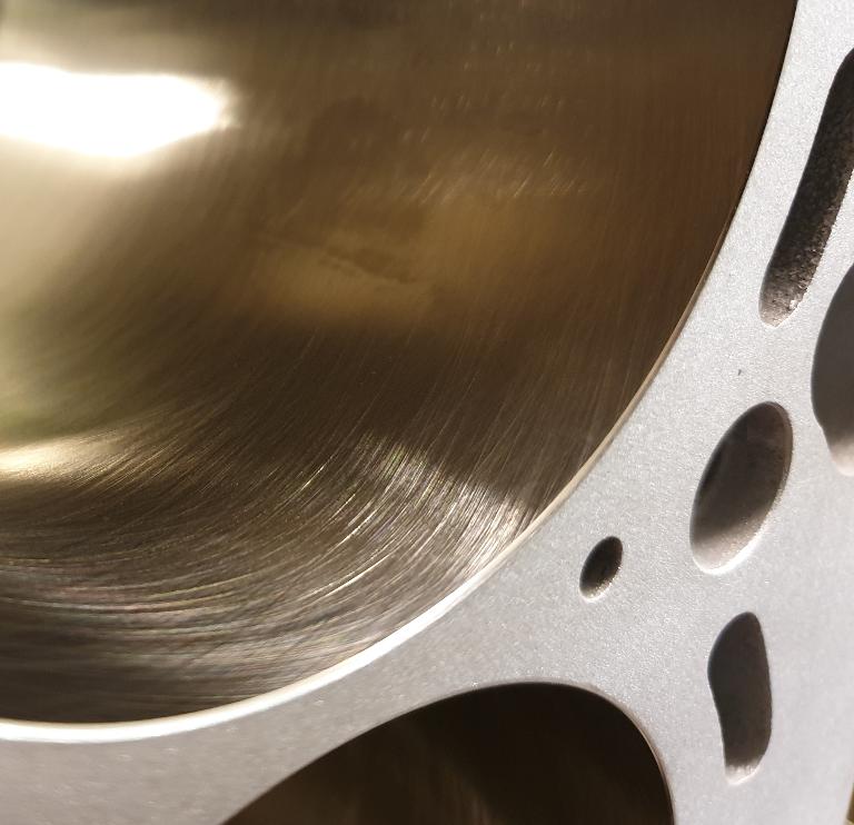
Nicasil coated cylinder liners
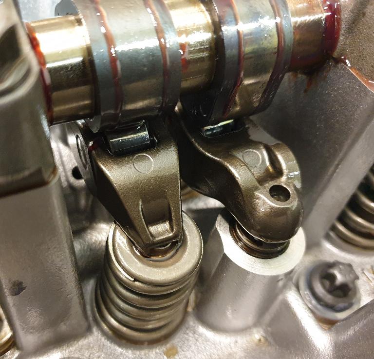
OEM roller rocker valvetrain
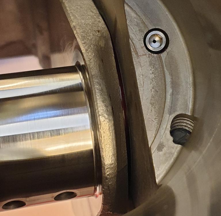
Piston cooling nozzles
Undressed, and not quite ready. The intercooler cores are hidden inside top plenums.
Complexity
With reference to the main issue, namely choosing the right base engine, we believe that the less complex engine unit, the better. Despite that it is a V12, it is not necessarily a complex engine. In our opinion, aircraft engines do not necessarily need four valve cylinder heads, variable camshaft or variable valve lift technology. Those types of powerplants are a lot more complicated, both mecanically and hydraulically, but also in the way one needs to control those systems electronically. Besides that, these types of engines gain a lot of unnecessary weight and size, which does not serve an aircraft well. It is also important to understand the reasons why these more complex systems have made their way to automobile engine propultion. You probably know why. The key words is; less emission. Of course, who wants to burn more fuel than necessary, and by that, to pollute more than we need! One of the reasons why we are leaning our aircraft engines is the fuel cost! That is the exact same reason why car manufacturers started making complex valvetrains like four valve cylinder heads, variable camshafts, catalytic converters, EGR (Exhaust Gas Recirculation) and rather complicated engine managment systems to control all of these add-ons. Reduced fuel consumption gives less pollution and the engine will be more efficient, efficient in terms of being able to burn as little fuel as possible under all kinds of driving conditions. There is no doubt that the car manufacturers have succeded in evolving their engines! They have actually done a pretty good job over the last thirty years! On the other hand, regarding the aircraft engine, starvation would lead to huge problems and dangerous situations. The driving conditions related to a car engine, are totally different in comparison to the flying conditions and the load of an aircraft engine, and can be seen as two extremes. Lets find ut why.
Lambda 1
In the beginning of 2000 a yardstick was introduced by the EU government in collaboration with fossil fuel combustion engineers. The yardstick that the engine manufacturers had to work out from, Lambda 1, shoud now be the new guideline that any engine manufacturer had to follow. Lambda 1 is describing a mixing ratio between air and fuel. The ideal mixture of air and fuel, which is 14,7 parts of air to 1 part of fuel, will give a chemically complete combustion where there is no remaining hydrocarbones left in the exhaust gasses. That is good news! Also there is a problem with this, because that very lean mixture will only propell your car down the road under ideal conditions. As soon as you are adding any weight to your car, accelerating just slightly to gain higher speed, climbing up a hill, or attaching a trailer to your car, the Lambda number will start decreasing rapidly, which means that your air/fuel mixture is off from the idealistic EU figure, meaning that you are burning more fuel than you should! Basically, your car engine is not capabel of "doing very much" under the influence of the Lambda 1 condition! Now, lets' say, for a reason or other, you would like to accelerate hard down a long straight road. Because of some special circumstances, you can keep the throttle at wide open as "long as you want". Your automobile engine is now performing more or less like an aircraft engine at take off and climb out. At a 100% throttle, neither the auto engine or the aircraft engine in this excample can opreate under Lambda 1! If one were to let them, they would literally burn up because of the lean mixture of air and fuel. Because of this lean situation, the combustion temperature will rise to an uncontrolled high temperature, and start melting down pistons, valves, cylinders and cylinder heads. Under full load, and with a lean mixture like in this situation, non of these two engines will work and be safe to drive or fly with. And to your information, engine manufacturers would never let them run this lean either! The air/fuel mixture relationship will probably be in the 12,5 : 1 ratio for both of them to be operating safley. Then the combustion temperature will be under control without any risk of detonation and destruction.
I am getting closer to my point here; any engine under continous high load can not operate under Lambda 1 conditions. Modern powerplants made by the automobile industry need the ability to be able to regulate fuel consumption quite differently in comparison to an aircraft engine, since the loads normally are a lot less, and vary constantly. When you are driving your car under normal conditions in normal traffic, you are 95% of the time below a 25% throttle opening. As a curiosity, it takes about 14 Hp to propell a modern car down the road in 80 Km/h or 50 Mph. Lambda 1 will most likely be sufficient. The aircraft engine on the other hand, operates more like a stationary power plant, running at a constant speed and with 65 to 100% as a normal operating load, from take off and until you are entering base leg before landing! Lambda 1 is then out of the equation.
Simplicity
We have deliberately chosen a less complex engine because of the higher rpm and load conditions an aircraft engine is operating under. There is a marginal need for any variation in the valve timing, valve lift, or even the ignition settings, when the engine is basically running under constant rpm and load. If the engine is designed and tuned to work under these "normal" operating conditions, we don't see any reason to introduce the complexity that a modern emission type engine would have. I am often thinking that when you are adding something to your aircraft that you maybe don't need, this something, which often is a part, has the ability to fail. If you have nothing, nothing fails, which of course is a stupid example, but hopefully it will make my point; to keep our creations as simple as possible!
No race engine characteristics
It is also important to understand that we are not looking for race engine characteristics in our aircraft engines. As an example, we are not changing or regrinding our camshafts to gain better efficiency at a higher rpm. We know for a fact, that the type of base engine we have chosen, can actually tolerate a relatively high rpm setting without beeing harmed by it. Still we would like to be able to reduce the engine speed to a more conservative rpm setting in combination with moderate boost levels instead. High rpm, which quite often results in high piston speeds, and in combination with high boost levels, can easily be a killer combination.
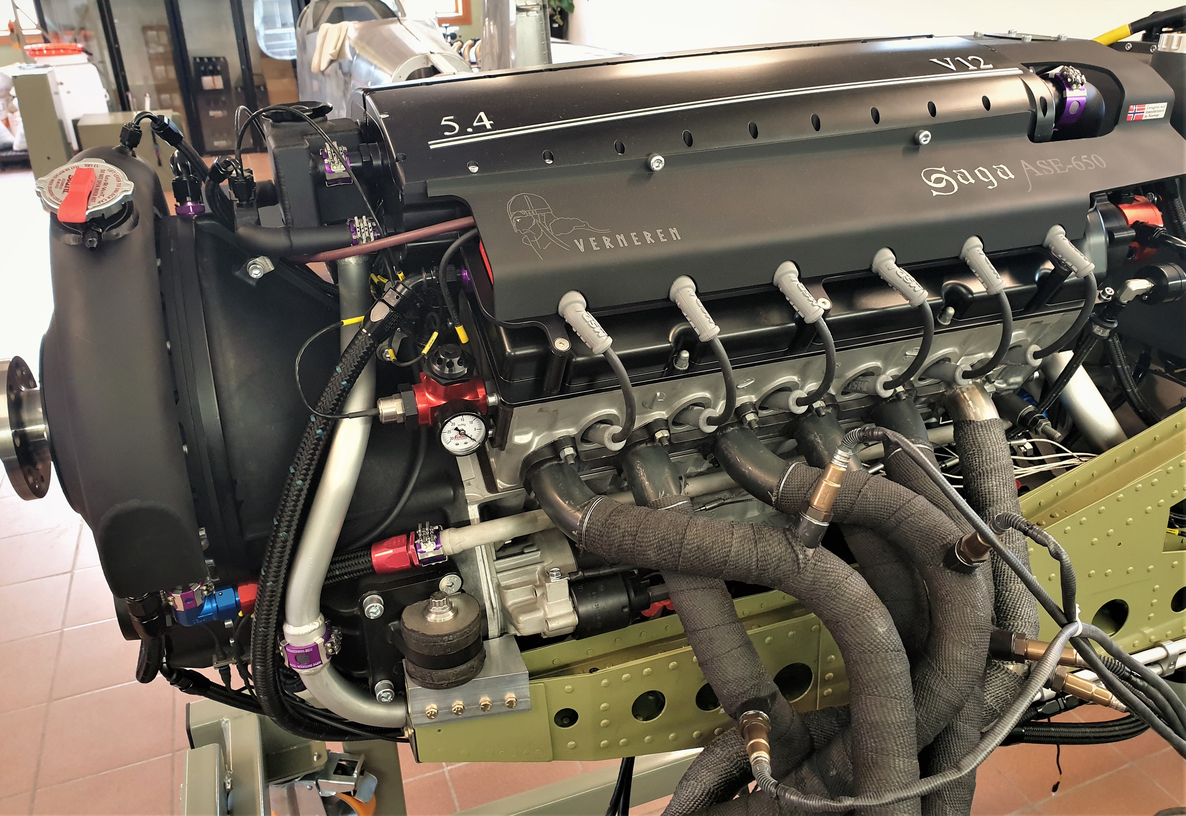
The ASE-650 Saga is missing the propeller in this picture, but you can most likely spot the Mark 15 PSRU. Also we have incorporated one Lambda sensor in collaboration with an EGT sensor for each cylinder. The Lambda sondes will be taken off after the testing period is over.
The importance of an even-fire ignition cycle.
As already mentioned, the base engine, or rather what's left of it, (block, crankshaft and heads) is borrowed from BMW's V12 production in the period from 1991 to 2003 with factory code M73B54. One of the most important factors regarding V12 development and engineering, is the fact that the block needs to have a 60 degree V configuration together with an associated 120 degree cranckshaft. One wants to spread out the ignition cycles evenly, or more precicely, every 60 degree of crankshaft rotation for a V12 engine. This is what is called an even fire V12. This is actually the only way to design the basic principles in a V12 correctly. If we look at ANY of the big engine manufactureres through the history who has designed and manufactured V12 engines, you will see that all of them are engineered in a 60 degree even fire configuration! To mention a few of the aero engine manufacturers: Allison V-1710, Rolls Royce Merlin 1650, Mercedes Benz DB 605, and also some of the V12 Car manufacturers are: Rolls Royce, Mercedes Benz, Ferrarri, Jaguar, BMW, Lamborgini, and Aston Martin.
Most of the warbird replica community are aware of the fact that a 90 degree block with a 120 degree crankshaft has been used by a few small V12 engine manufactureres, most likely to avoid a costly and long term development program. This short cut is of course tempting in view of the economy involved in such a huge project, but as several airmen in the high performance experimental community have experienced, this shortcut has lead to dangerous and really unhealthy situations! Even fatal accidents.
The problem with the odd-fire ignition cycle
The following facts are explained very well on Mr. Jack Kane's web pages: http://www.epi-eng.com/piston_engine_technology/torsional_excitation_from_piston_engines.htm, and with his permission, I will try to give an account of his studies of the odd-fire ignition cycle below.
Certain examples of odd-fire engines exhibit an unexpected characteristic. When one cylinder follows its predecessor very closely, the successor puls combines with its predecessor puls to produce a single larger torque pulse, and the output waveform changes to the order of an engine with half the number of cylinders. Therefore the excitation frequency is half what an evenly- spaced V12 engine produces, and the amplitude is considerably greater.
A specific example of the phenomenon is the 90 degree V12 engine being used in a certain P-51D warbird replica aircraft. That odd-fire engine is, in essence, a pair of in line six-cylinder engines, physically separated 90 degree from each other, but sharing a common 120 degree crankshaft. This engine has a 90 - 30 - 90 - 30 degree fiering impulse spacing.
.jpg?v=1566465869914)
.jpg?v=1566561857074)
Technical spesifications & Performance data
.jpg?v=1610183973131)
Technical specification
- Engine type: 60 degree even fire V12
- Engine code: M73-B54
- Cylinder block: AluSil, with NicaSil coated cylinders
- Bore: 85 mm / 3,346 Inch
- Stroke: 79 mm / 3,11 Inch
- Displacement: 5379 CC / 330 Cid
- Compression ratio: 8,0 : 1
- Cylinder bore center distance: 91 mm
- Valvetrain: SOHC, chain driven
- Pistons: Aluminum, custom CP with CT-3 Hard Graphite coating
- Connecting rods: Auto Verdi
- Connecting rod length: 135 mm
- Connecting rod / stroke relationship: 1,708
- Fiering order: 1 - 7 - 5 - 11 - 3 - 9 - 6 - 12 - 2 - 8 - 4 - 10
- Oil capacity: 16 Lt / 4,25 US Gal
- Lubrication system: Auto Verdi dry sump system, external reservoir
- Idle speed: 1200 RPM
- Max take off speed: 5000 RPM
- Mean piston speed at 5000 RPM: 13,16 m/sec / 2590 ft/min
RPM HP TORQUE BOOST
3000 RPM, 304 Hp - 532 Lb-ft / 723 Nm @ 10,4 Psi / 0,73 Bar
3200 RPM, 340 Hp - 559 Lb-ft / 760 Nm @ 11,7 Psi / 0,82 Bar
3400 RPM, 379 Hp - 586 Lb-ft / 797 Nm @ 13,0 Psi / 0,91 Bar
3600 RPM, 423 Hp - 617 Lb-ft / 839 Nm @ 14,3 Psi / 1,00 Bar
3800 RPM, 466 Hp - 645 Lb-ft / 876 Nm @ 15,7 Psi / 1,10 Bar
4000 RPM, 511 Hp - 671 Lb-ft / 913 Nm @ 17,1 Psi / 1,20 Bar
4200 RPM, 548 Hp - 685 Lb-ft / 931 Nm @ 18,5 Psi / 1,29 Bar
4400 RPM, 588 Hp - 702 Lb-ft / 955 Nm @ 19,7 Psi / 1,38 Bar
4600 RPM, 621 Hp - 709 Lb-ft / 965 Nm @ 21,1 Psi / 1,48 bar
4700 RPM, 639 Hp - 714 Lb-ft / 970 Nm @ 21,8 Psi / 1,53 Bar
4800 RPM, 656 Hp - 718 Lb-ft / 976 Nm @ 22,5 Psi / 1,58 Bar
4900 RPM, 666 Hp - 713 Lb-ft / 970 Nm @ 23,0 Psi / 1,61 Bar
5000 RPM, 675 Hp - 709 Lb-ft / 964 Nm @ 23,5 Psi / 1,65 Bar
5100 RPM, 682 Hp - 702 Lb-ft / 955 Nm @ 23,9 Psi / 1,67 Bar
5200 RPM, 683 Hp - 690 Lb-ft / 938 Nm @ 24,2 Psi / 1,69 Bar
Mean Piston Speed
The maximum allowed engine revolutions for the ASE-650 Saga is set to a fairly conservative 5000 RPM! At that specific RPM our engine has a Mean Piston Speed (MPS) of 13,16 m/sec or 43,18 feet/sec, which is equivalent to 2590 feet/min. There is a general rule of thomb regarding maximum mean piston speed for engines used in aircraft service. That maximum MPS speed is at a "comfortable" 15,24 m/sec or 3000 feet/min. It takes approximately 5800 RPM to reach that MPS for the ASE-650 Saga. Experience has shown more than ones, that exceeding the MPS speed value substantially have given relability issues!
For those of you who want to go in a little deeper
Below, you will find several different topics to choose from if you are interested in knowing more about how we have treated the base engine to a level where it can be used as an aircraft powerplant. Put your pointer over the topic you are interested in and click on it. A new page will then open up with more information and pictures to describe in more details the topic you selected. Enjoy!
.png?v=1612784827976)
Connecting rods
.png?v=1612784890404)
NicaSil coating
.png?v=1612784888441)
Compression ratio
.png?v=1612784890490)
Pistons
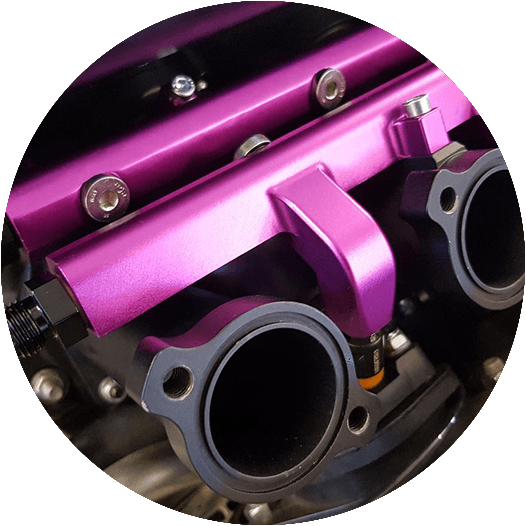
Induction system
Fuel system
Hydro elements with OEM roller rocker arms for less friction operating valve train.
.png?v=1612784897835)
Supercharger
.png?v=1612784892237)
Engine managment
Dual independent engine management system solution with full line of sensors for each ECU.
.png?v=1612784896506)
Valve springs
.png?v=1612784896303)
Piston Cooling Nozzles
.png?v=1612784896748)
Cylinderheads and Valvetrain
.png?v=1612784888381)
Block and Crankshaft