.png?v=1611050572224)
.png?v=1611050431932)
.png?v=1611050548824)
.png?v=1611050119333)
.png?v=1611050465355)
.png?v=1611050452767)
.png?v=1611050558000)
.png?v=1611738745088)
.png?v=1611050528853)
Cylinder heads & Valvetrain
The cylinder heads are almost as BMW delivered them from the factory. The engine is equipped with single overhead camshafts, operating one intake and one exhaust valve pr. cylinder. The camshaft and lifters are of roller type from the factory. We deliberately chose these engines because they do not use Vanos / variable camshaft timing, nor Valvetronic / variable valve lift. The next generation of the BMW V12 engine, the N73-B60, has these functions, which make them wider because of the "four valve pr. cylinder" head design. It would therefore be very hard to make this type of engine fit inside the cowling in a scaled Mustang, Spitfire or similar. The N73-B60 is also a lot heavier because of the more complex design.
As you might be able to see from the picture to the right, BMW has incorporated a vulcanized steel and rubber insulator between the inlet manifold and head. This simple device prevents heat dissipation from the cylinder head into the 12 individual intake runners. The insulators also prevent the majority of any vibration led into the inlet manifolds and intercooler plenums. The bending forces exerted by the weight of the plenums together with engine vibration will have a tendency to impact the mounting flanges.
Camshafts
The camshafts in this powerplant are also as they come from the BMW engine factory. In other words, they are not reground to change the characteristics of the engine. In the situation where this engine is normally aspirated, the OEM camshafts give maximum power at 5000 RPM, and maximum torque at 3900 RPM, which is in line with our thoughts regarding the maximum engine operating RPM. Another advantage by using the original camshaft profile from a modern V12, is that one retains a smoothly operating engine through the designated RPM range. Another advantage with a "not so hot" camshaft, is that the combustion pulses will be of a more even character, which is excellent, considering that the power will be transferred to a Propeller Speed Reduction Unit and to the propeller.
For those of you who are especially interested in camshaft specifications and their values, you will find them below.
Intake Valve
- Open Duration - 240°
- Lobe Separation - 112°
- Lift - 10,3 mm
- Valve Diameter - 42 mm
Exhaust Valve
- Open Duration - 240°
- Lobe Separation - 109°
- Lift - 10,3 mm
- Valve Diameter - 36 mm
Roller rocker arms
BMW has chosen a Roller Rocker Arm to actuate the valves. The use of roller rockers in place of a solid rocker arm, allows for a more agressive camshaft profile and reduces the overall rotating friction in the valvetrain. The camshaft lubrication is supplied by oil distribution rails mounted to the top of the bearing caps. These rails will ensure precise lubricating oil distribution directly onto the individual camshaft lobes.
Chain & Camshaft driven pumps
The camshafts are driven by a single row chain. In our powerplant, the chain also has to drive two additional pumps, which again are mounted on to the end of each camshaft. We needed a mechanically driven fuel pump and also a water pump to circulate the fluid for the intercooler system on the other side. In the absence of the OEM distributors, which left two empty spots at the front end of the engine, we where immediately tempted to use the empty spaces for something useful. As indicated above, we knew from early design stages that we would like to incorporate a mechanically driven fuel pump in addition to the electrical ones, and also a mechanically driven water pump to circulate intercooler water. Maybe the camshafts could run these pumps? In the beginning we were a little reluctant to embrace this idea, because we thought that the chain had enough "work" going on, pulling the camshafts. Pulling a camshaft is not the most pleasant job inside an engine. Think about it, first of all it is a heavy load, and secondly, the chain is under a constant pulsation from the camshaft lobes opening and closing valves under high spring pressure!
Anyhow, after further considerations, we found out that two small pumps, pumping a low volum of liquid at fairly low pressures could not do any harm. Actually, we believe that these two pumps will slightly decrease the strain going through the chain. First of all, the two pumps together will draw less than half a horse power. Secondly, we believe that the pressurized fluids inside the pumps, will tend to work as a pulsation dampener for the camshaft chain.
Sealing combustion pressures
It goes without saying that the combustion pressures within a supercharged powerplant are higher than in a normally aspirated powerplant. Sealing of combustion pressures can somtimes lead to challenges. An OEM gasket is designed to seal pressures made for the application it is set to serve. Exceeding the gasket limitations quite often leads to what we know as a "blown" head gasket. This situation results in trouble like combustion pressure leaking into the cooling water "jacket", water mixing with lubrication oil, or lubrication oil mixing into the water cooling system. In other words, a lot of unnecessary hazzle!
Today, there is broad knowledge on this spesific topic. There are several aftermarket companies that make great gasket solutions to help preventing combustion leak problems. Among them are the multi-layer gaskets made by companies like Cometic. There are other solutions where implementation of an especially designed gas filled ring machined into the block or the cylinder liner that gives excellent results. Another variant is the Vulcan Cut Rings used together with a composit gasket material for sealing off oil and water passages between the cylinder head and the block. This system is manufactured and sold by the American company SCE, www.scegaskets.com If you are interested in learning more about their sealing products, take a look yourself.
The steel O-ring solution
Instead of having a specialized gasket company making a complete gasket set for our powerplant, we have chosen to use the OEM gasket in combination with steel O-rings machined into the cylinder head. This is a known and well proven technique, and has shown good sealing results in many different "high boost" applications. The Norwegian M73-B54 V12 guru, Per Kristian Harildstad, has done the machining of the O-ring groves, and he also installed the wires into the grooves in the cylinder heads. The ideal protrusion of the wire is somewhere between 0,2 to 0,3 mm / 0,008 to 0,012 Inch. The point with this solution is to put "spot" pressure excerted by the steel O-ring onto the fire ring in the OEM gasket. Since the contact point of the steel O-ring is very slim compared to the surface of the fire ring in the original gasket, the contact pressure will increase substantially between the steel O-ring and the OEM fire ring. Actually, after the heads are torqued down over the head gasket onto the cylinder block, the high pressure makes the steel O-ring squeeze into the metal in the fire ring. Take a look at the two bottom pictures to the right, and you will get an idea of how this technique is
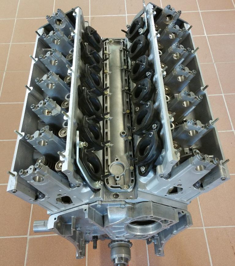
Obviously no camshafts are installed into the heads in these picture! As you can see, this is a single overhead camshaft cylinder head, controlling one intake and one exhaust valve pr. cylinder.
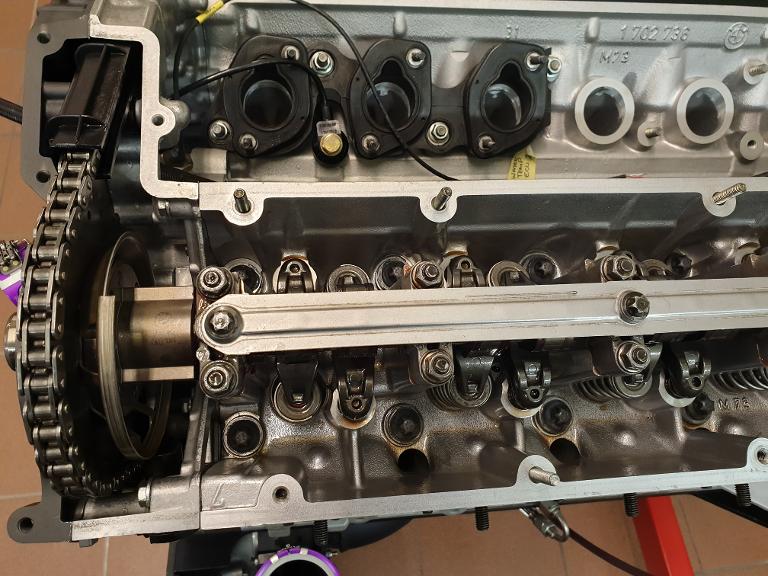
At the very top in this picture, you can spot one of the heat and vibration insulators. Also one of the four knock sensors can bee seen. The "lubricating rail" is mounted right above the camshaft, so oil can be sprayed directly onto the camshaft lobe through designated holes.
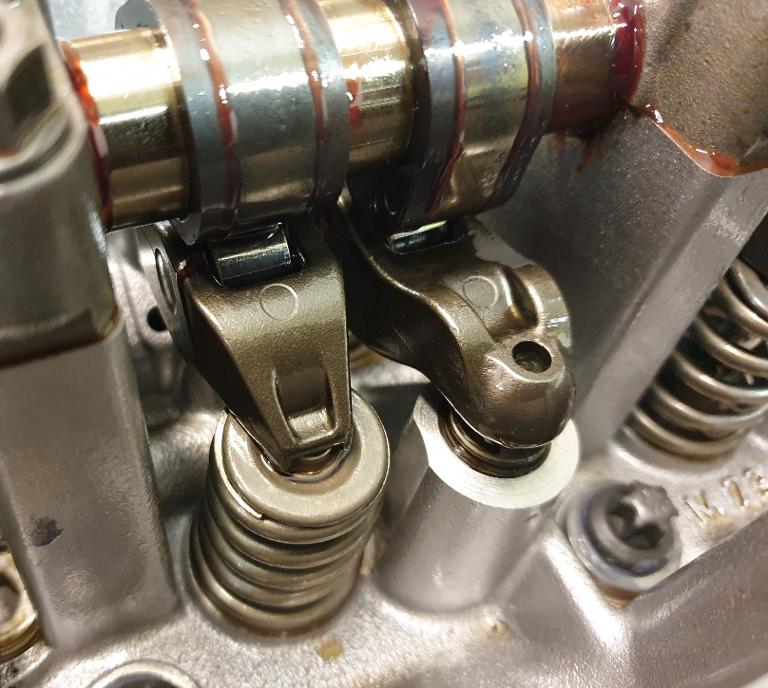
If one looks closely, one can spot the roller wheels on the roller rocker arms. The spring and rocker arm to the left is actuating the intake valve, and the hydro element to the right is making sure to actuate the rocker arm and lift the exhaust valve on the other side of the camshaft.
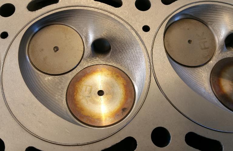
The cylinderheads are "O-ringed" to make a better seal against the OEM gasket.
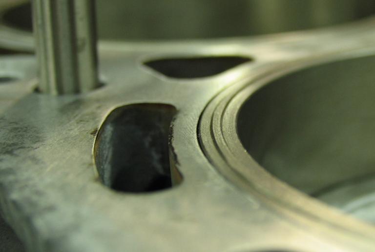
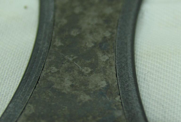
working. To your information, these pictures are from another similar project that we did some years ago with a Toyota 1Uz-Fe V8 engine. This is just to illustrate the result from the impact that a similar type of "high pressure ring" has on a OEM composite head gasket. In this example, we machined a ridge into the cylinder liner instead of machining a groove for the steel O-ring into the head. You can most likely spot where the ridge in the cylinder liner has exerted the most pressure. Excactly where one wants the pressure to be, in the center of the OEM gasket's fire ring.