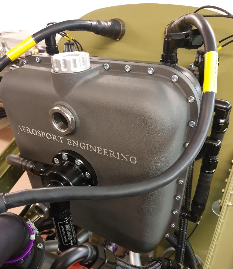
The All Attitude Oiltank & Lubrication system
We have designed an oil and lubrication system specifically for this engine and type of aircraft, namely the scaled down Mustangs, Spitfires and similar. The whole system is based on dry sump principals where the main oil tank is separate from the engine. The crankshaft is driving a pump with one pressure stage and multiple scavenge stages. The pressure stage is lubricating the engine, the supercharger and the Propeller Speed Reduction Unit, (PSRU) while the multiple scvavenge stages are sucking aerated oil back into the main oil tank after the lubricating process. The dry sump pump from Auto Verdi AB www.autoverdi.com incorporates a separator mounted to the end of the unit, through which all the oil/air has to pass before it is returned to the tank. The benefit of this operation, is that the oil which is returned to the tank will be of a more homogenious consistency than the oil which will be returned from a system without a separator.
The air which is separated from the oil will be directed to a designated air chamber, from which it will be ventilated out. The separating process starts at approximately 2500 pump revolutions. For your information, the dry sump pump in this system runs at 84% of the engine RPM. A more commonly used pump speed would be closer to half the engine speed. This engine has a maximum "take off" and operating speed of 5000 RPM, which is quite conservative compared to for excample a Nascar Cup veichle running at or above 9000 RPM. Therefore we would like to gear our pump to run faster to get the separator up to speed where it can maintain a continous positive deareation of the oil.
Flying in all attitudes
In an attempt to meet the requirements of flying safely in all attitudes, there are a few more issues to deal with. I had this vision of being able to fly safely up side down, macho as it may be. One must understand that the dry sump pump, hoses, fittings and oil pan are not the issue here. It is the oil tank which requires most of the thorough scrutiny and consideration. More or less an entire year was spent thinking and drawing up ideas, rejecting them, starting over with new ideas and redesigning old ideas to get where we are today. It has been a challenging process, but mostly a very inspiring and interesting project.
The oil tank itself, which has a shape similar to the original Mustang tank, contains four chambers, one main oil chamber, and three different «breathe out» or ventilation chambers. The system also includes three different swivels for picking up oil and ventilating out air in all flying attitudes. There are two sides to this challenge, firstly, the easy one, which obviously is to provide oil to the main pump, and secondly, the harder task, to ventilate excessive air produced by the «blow by» gasses from the engine, out of the tank. If you fail to ventilate the tank, it will eventually explode.
The seven scavenge stages are evenly distributed where they are needed. There are three larger scavenge stages mounted directly to the oil pan, which means, no connecting hoses between the pumps and the oil pan. This solution prevents leakage. There are two stages connected to each valve cover in order to be able to drain them when flying inverted, since the valve covers then function as bottom pan. Another stage is draining the PSRU unit, and there is also one stage for the supercharger drainback oil.
A smaller AN6 hose is routed in to the supercharger drain back area (picture 5) from the bottom of one of the «breathe out» or ventilation chambers in the oil tank. There are a couple of rasons for my choice for this solution.
- If the air ventilated from the oil tank is contaminated with oil or oil fumes, due to for example rough air, this will be sucked back into the system through the supercharger scavenge stage through a calibrated orifice in the tank.
- The other necessity, regarding draining oil upstreem from the supercharger in to the scavengepump, is to let air into the suction area. Captured vacum will not put oil into motion, it is pressure differensces that will make the oil move toward the vacum source, and therefore it is of importanse to let air into the system to help the vacum lifting and finally catching the oil. The air is bleeded in to the system from the 1 atmosferic source in the breath out tank, where the drainback area for oil coming from ventilated air is located.
The Swivel strategy
Once again I would like to emphacize that we are trying to avoid designing highly complex parts, or systems. We have tried to implement the same thoughts throughout the design process of our "All Attitude" oil tank. After a few attempts with various results, we found out that a swivel design could be a solution to solve this task. Right from the start, I was hoping that we could have engineered a system with fewer parts, but after some considerations of the other design ideas that we had made earlier, we understood that this was the most secure path to try out.
As you already may have understood, this system contains three different swivels. You can see them in picture 4 and 7. The main swivel is mounted horisontally in the senter of the tank, and can swivel 360 degrees in both directions. As you might see from the pictures, there are also two vertically mounted swivels in connection with the main swivel, one bigger and heavier swivel in the bottom of the tank, typically AN16 standard, and a smaller and much ligther at the top of the unit.
The bottom swivel is as mentioned, heavier because of a weight is mounted to it, making sure that the oil suction pipe always will be at the very bottom of the tank in any attitude. So, lets imagine that you are performing a roll in you aircraft, where the roll rate does not matter. The oil suction pipe, which is the heavier part of the assembly, will always be located close to the bottom of the tank. It will be held stationary at the bottom, while the aircraft rolls. While the aircraft is moving in the roll axis, the bearings inside the horisontally mounted main swivel also rolls, to keep the main oil suction pipe stationary at the bottom of the tank.
Now, lets take a closer look at the vertically mounted swivels. Both are working by the same principal, but they are adjusted to work in totally opposite directions. Firs of all, they can also swivel 360 degrees around their own axis, in both directions. The oil pick up swivel at the bottom, is, as mentioned, always pointed to the bottom of the tank. Let's imagine once again; you are on "climb out" in your properly modified Thunder Mustang, and you are wondering how steep you can climb without getting into oil starvation because of your nose high attitude. If your imagination is working properly, you would be very calm, because you can "see" that the heavier oil pick up tube swiveled into a "pointing backwards", or rather, more down position, which again is where the tank, in this situation, is at its deepest. The opposite happens in a steep decent. The weight of the oil pick up tube will swing the swivel immediately to a "pointing forward" or, down to the bottom of the tank, position.
At the top of the tank, you will find the "air out" swivelling tube. As we learned, this can also swivel 360 degrees in both directions. This, on the other hand, has the weight mounted on the oppsite side, or as far away from the "air out" tube inlet as possible. With my expression "air out" I am trying to describe that this is the point where the air is ventilated out of the tank. This is THE most crucial part in the whole assebly, and for the same reason, we don't want oil into this system! The "air out" tube, which is of AN10 size, is always striving to stay as high above the oil level as possible, or, in other words, as high as possible up in the layer of air where oil can not get to the opening of the "air out" tube. To point that out a little further, the tube is almost reaching all the way up to the ceiling of the tank. So, lets imagine again, that you are in the same "climb out" as you were in before, and.... excactly, you got it, the "air out" tube inlet is pointing in the totally opposite direction of the oil pick up tube! It is pointing in a "forward and up" position, and by that, as far away from the oil sea as possible.
As you now understand; when the pilot flies the aircraft into whatever position or attitude he chooses, all of the swivels will move right away, correcting their positions to the better, which again leads to; a safe lubrication of the engine components, and a good ventilation of the blow by gasses, not caught by the piston rings. This whole assembly is maybe what we could call a gravity system.
The maximum amount of oil that you can safely add to the main oil reservoir is 10 to 11 liters/quarts, but one can fly with a lot less than this amount without getting into trouble. The total weight of the unit with most of the fittings and hoses, but without oil is: 22 Kg or 48,8 Lbs.
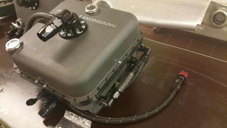
In the picture to the right you can spot the main swivel/oil out connecting point, which is the AN16 part mounted in the middle of the front cover. We have designed two different versions of the main oil out connecting point. The one installed on this tank is with regard to narrow installations where engine components may come in conflict with the tank itself. All tanks are anodized in black.
From valve covers to bottom pans

Flying in all attitudes
Flying inverted is really not that necessary. It can be unpleasant, disorienting, and a very different experience when you're not used to it. It can also be quite dangerous if you don't know what you are doing. On the other hand, if you are trained to do it and keep up your training level to stay confident, it can be quite inspiering, fun, and of course, very macho!
The mechanical aspect
There are at least a couple of reasons why I got inspired to construct a lubricting system that works in any flying attitude. First of all, I really enjoy flying aerobatics! Together with my excellent instructor, Helge Storflor, and the right amount of training, one eventually becomes a much better pilot. Coordination is key, and just like any thing else, it takes practice to get better. The second, and the most weighty reason for my commitment to this specific part of the project, is my interest in how the mechanical aspect of it can be solved. I am more of an engineer than a pilot, and I must admit that I am intrigued by solving mechanical challenges. I really enjoy finding the simpler solutions to the problems that arise in mechanical contexts. Also the fact that the original Mustangs and Spitfires could not fly with negative G for more than twelve to fifteen seconds, makes this challange even more interesting.
The valve covers
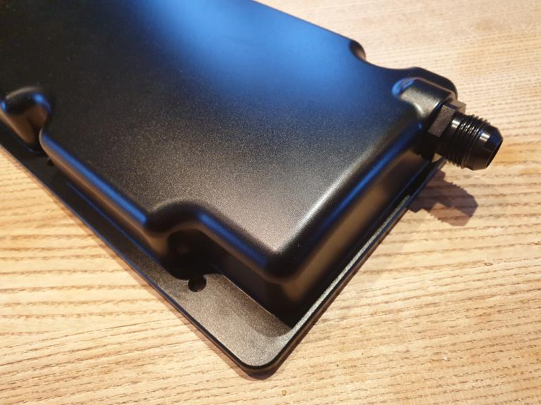
Anyhow, the valve covers in our ASE-650 Saga powerplant, are designed so that they will work as "bottom pans" during sustained flights in an upside down attitude. They are beautifully machined, from billet 7075 aluminum alloy, and anodized in black for protection against the harsh Norwegian wether. From the first two pictures to the right, you might get the understanding that the oil suction point is placed in the center of the cover, and also that it will be at the lowest point when the engine is "turned" up side down, or with other words, is inverted. In the lower picture to the right you can se the AN10 male attachment point where one can fit a matching fitting and hose to route down to a designated scavenge stage. There is one scavenge stage for each valve cover. Someone might ask if that is really necessary. Why wouldn't one scavenge stage alone drain both valve covers? The problem is, as soon there is air instead of a mixture of oil and air, which is heavier, then the scavenge stage will suck air from the pick up point in one of the covers, which, in turn, is not necessarily submerged in oil. With two separate valve covers, you will therefore need two separate scavenge stages.
Picture 2.
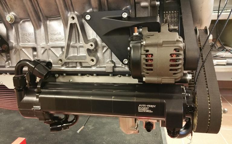
The Swedish company Auto Verdi, delivers top of the line dry sump pump systems. You can spot the oil & air separator at the end (left side) of the pump.
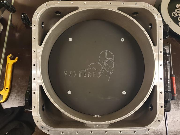
Picture 3.
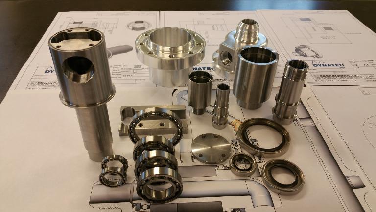
Some of the internal parts in the "All Attitude" oil tank system.
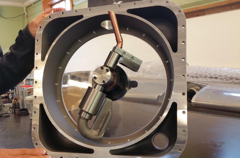
Picture 4.
Her one can see all three swivels mounted in the front half of our test tank. We added a lexan glas to be able to observe the functionality under the different aerobatic manuvers.
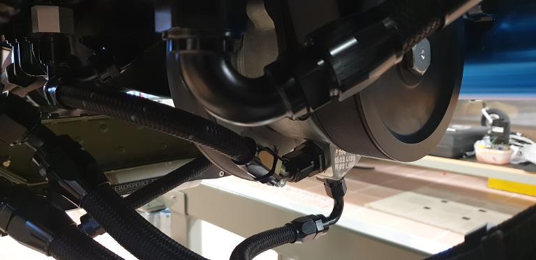
Picture 5.
Here you can spot the supercharger drain area with a AN8 oil return line to a designated scavenge stage. The lower AN6 hose and fitting is connected to the bottom "breath out" chamber in the oil tank.
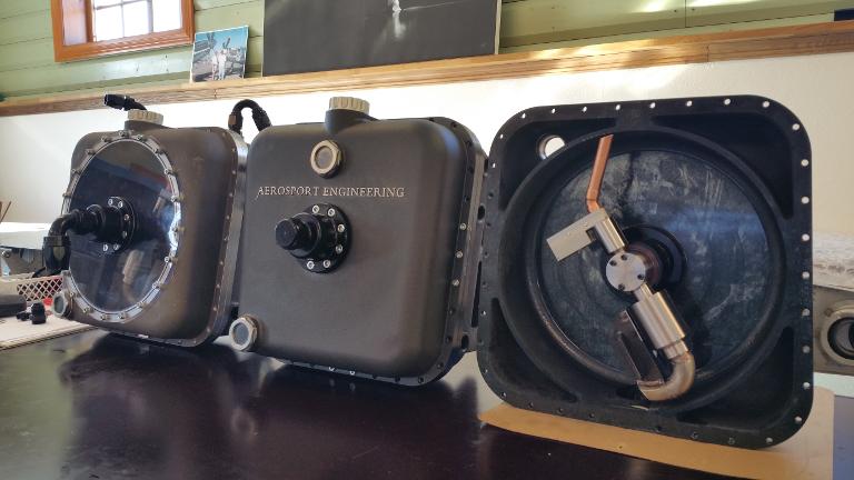
Picture 6.
This is the rear half of the tank, with the main oil reservoir in the middle, and three breathe out chambers around. The bottom air chamber is connected to the supercharger drain back area which again is connected to a scavenge stage.
Picture 7.
The tank itself is of a cast aluminium design. It also has a 12 degree built in mounting bracket on the rear half to simplify firewall installation. There are two sight glasses incorporated in the assembly. The upper is for making an easy visual check of the oil level, while the lower one in the corner helps diagnose for internal leaks, too high oil level, or trouble in the breathe out system.
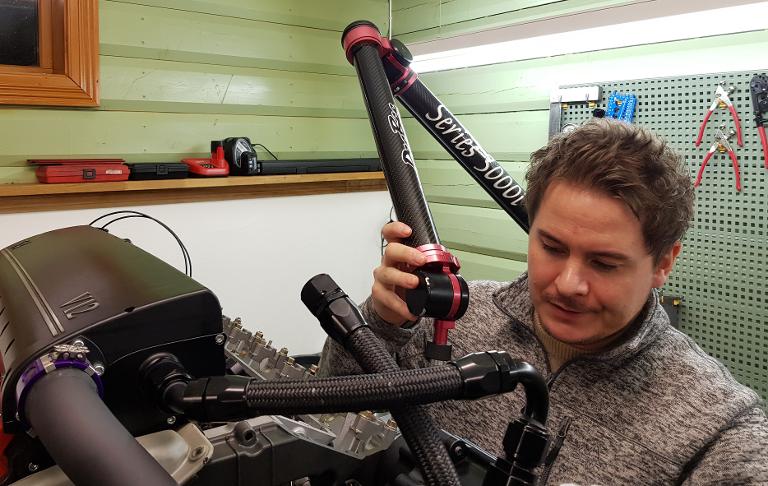
Petter Bøhn is a Norwegian engineer with the right equipment. Here he is tracing the foot print of the valve cover so that new ones can be made to our specifications.
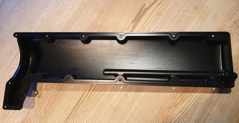
Here, the cover is up side down to expose the suction point in the middle and down in the cover.
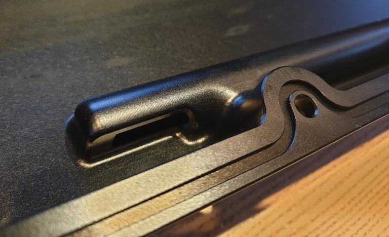
Here, the suction point is highlighted.
This is the connection point to where we mount a fitting and hose to direct the oil down, well, actually up if inverted, and into the scavenge stage.