.png?v=1611050572224)
.png?v=1611050431932)
.png?v=1611050548824)
.png?v=1611050119333)
.png?v=1611050465355)
.png?v=1611050452767)
.png?v=1611050558000)
.png?v=1611738745088)
.png?v=1611050528853)
The Supercharger
The ASE-650 Saga is a supercharged engine! We knew quite early in the design stages that this would be necessary, since the maximum power output from the M73-B54 as a normally aspirated engine is unsufficient. What we did not know, was the amount of work we had to put into this "supercharger project" to make the components involved operate as expected. Initially we had in mind that the supercharger system should have been described as a part of the induction system, under Induction in the menu above. Now, after the installation is done, we have chosen to make this separate supercharger chapter.
Why not a Turbocharger
Why would we bother implementing a supercharger when there are plenty of modern and sophisticated turbochargers in the market? There is no doubt about it, a modern turbocharger setup has great capabilities, quite often better than a supercharger. They have evolved steadily during the last thirty years, and the quality of the aftermarket units has also proven to grow remarkabley better than just a decade ago. There are a lot of options to choose from for almost any type of engine application, and it would be an easy task to find an appropriate turbocharger combination for the ASE-650 Saga powerplant. We would more than likely have had a better overall result, and a more agile powerplant with a turbocharger. There are still a few reasons for not going down this path, and we would like to highlight a couple of the most obvious ones.
Nr.1 The cowling issue
Mustangs and Spitfires have narrow cowlings since they used the Allison and Rolls Royce V12 engine. The scaled down replica have the same slim and narrow cowling, only smaller, to make it fit the scale. Our V12 engine is chosen specifically to fit these aircraft, and it fills up the space inside the cowling like the Allison and Rolls Royce do in the full size version. This means that there is not a lot of room left inside the cowling! At least not for any exhaust tubing to be routed down to where a turbocharger, or even two, would fit in! The cowling would have to be heavily modified to axcept six exhaust tubes between the engine cradle and the cowling on both sides of the aircraft. If so, this would have harmed the aesthetic of these beautiful warbirds.
Nr.2 Turbo heat
A turbocharger system produces a lot of heat compared to a superchager system. In a turbocharger system, exhaust manifold, exhaust tubes, turbocharger, waste gate routing and exhaust tip are glowing red as soon it starts to produce boost. Even if one can isolate the heat to some degree, the risk that someting may start to burn is much higher where a turbocharger system is implemented than if it were a similar supercharger set up. The fact that the space between the various components inside the firewall forward compartment is tight, and also the fact that engine compartment ventilation is restricted, makes it no better. Heat dissipation to surrounding components like fuel and oil lines, wiring harness and similar, can therefore be very problematic and out right dangerous! This is especially true in cases where the engine is liquid cooled, since the design and nature of the cowling has limited ventilation possibilities compared to the one in an air cooled engine installation. The heat dissipation within a supercharger system is far less, compared to the one in a Turbochager system, and most likely it will be a safer choice for a warbird replica.

10 rib K-profile belt, combined with generous diameter belt pulleys to avoid slipping.
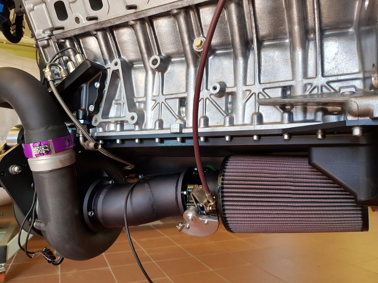
The throttle body is mounted in front of the Superchargers inlet. This instantly became a breathing problem! You can read more about the topic on these page.
We have incorporated a Adel Wiggins mounting flange on the superchargers outlet. This makes it a lot easyer to mount on and off.
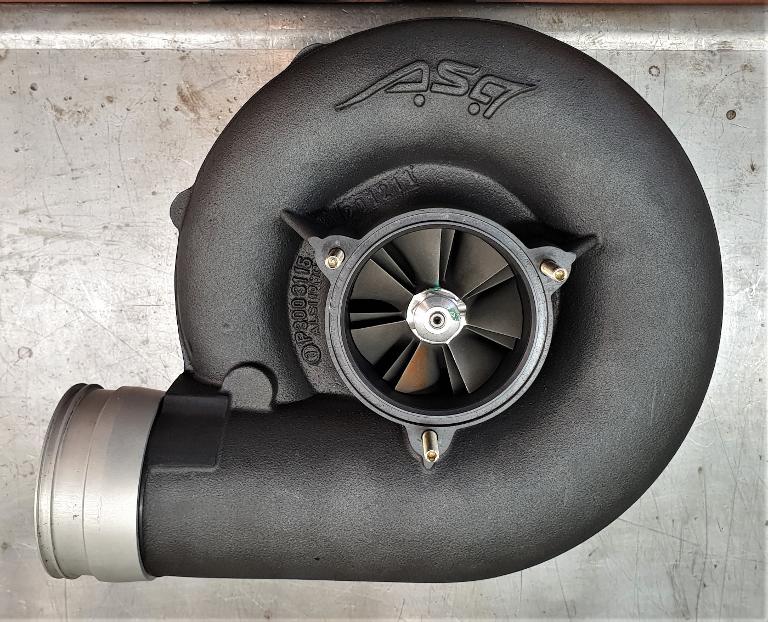
The ASA T1-724 Supercharger
The Supercharger is manufactured by the German company ASA Kompressor GMBH, www.asa-kompressor.com and the specific model we have incorporated is the T1-724, where 724 indicates the ideal level of power that the Supercharger can deliver. ASA Kompressor has a good reputation, and one will find BMW in their customer portfolio.
There were a couple of features that we found interesting with their supercharger, or Kompressor, as they call it. First of all, we liked the internal "step up" ratio which is 1:15. This means, if one turns the input shaft one revolution, this will turn the compressor wheel 15 revolutions. We don't know any other supercharger producer with anything close to this step up ratio. This is achieved with the help of an especially designed planetary gear set. The advantage of a steep step up ratio is that one can get the impeller speeds right up to the ones installed in similar sized turbos. The maximum impeller / compressor "wheel" speed allowed for this supercharger is 100.000 RPM. The obvious reason for the manufacturer to go down this path is that the choice of impeller variants opens up. Another not so obvious reason to use a steep internal "step up" ratio, is that the installer can make use of a larger diameter pulley on the Supercharger unit to achieve the same high compressor speed. The benefit with lager pulleys, especially on the supercharger, is to keep good contact with the driving belt, and by that, avoid slipping.
Induction restrictions
Another interesting feature with the ASA Supercharger is that one can put the throttle body in front of the impeller without doing any harm to the rest of the supercharger. We really liked this idea, mostly because we could eliminate one more component in our set up, namely the dump valve. The dump valve looks exactly like a waste gate, but the work it does in a supercharger set up is a little different from what it does in a turbocharger set up. Anyhow, we do not need a dump valve when the throttle body is mounted in front of the supercharger impeller. The "butterfly valve", or throttle plate, is the mechanical restriction for the air allowed into the supercharger impeller, and thus the supercharger will not compress more air than the volume of air that passes through the butterfly valve opening. When the butterfly valve is in near closed position, meaning idle position, the superchager compresses just enough of the air that passes the butterly valve, so that the engine will still run at idle speed. One must understand that there will be vacuum between the closed butterfly valve and the supercharger impeller. Even at a wide open throttle, one can measure vacuum if any of the induction components have flow restrictions. We have found that restrictions on the inlet side of the supercharger will cause a wider range of problems than if the restrictions were to be found on the pressure or oulet side of the supercharger. It is really amazing how a small "imperfection" in an inlet manifold can make such a huge difference in power output.
Sir Stanley Hooker
As a curiosity, I can mention that Sir Stanley Hooker, encountered the same challenges with the Rolls Royce Merlin! He fought that problem from the very start of his work on the induction system in 1938 and towards the end of the war in 1945. Eventually he really succeded. He gained close to a 1000 Hp during those years, and only by concentrating on his work with the induction system and the supercharger. Mr. Hooker was a remarkable man, and I really admire the excellent work he did in the field of aviation propultion. Every one that is interested in engines should read his book: Not much of an Engineer.
Modifying a good product
There is nothing wrong with the ASA supercharger, except for the fact that it might be just a tad to small for the job it is set to do. In other words, we don't think it produces enough air for our 5,4 Lt / 330 Cid engine. The external dimentions of the supercharger fits perfectly to the engine and to the rest of the installation in the firewall forward package. Based on the good qualities we appreciate in this supercharger, we admit that we went a little "blind" when it came to the actual performance data of the unit. We were "wishing" it to perform better than the pressure map data, shown in the picture, a little up and to the right. After the first dyno session, we concluded that we were running out of air. The boost pressure started to drop off to early, and continued to fall rapidly after 4600 RPM! We also measured 6 Hg of vacuum right in front of the supercharger impeller, at wide open throttle. This information told us that we might have a restriction somewhere in front of the supercharger impeller. But where, and what kind of restriction? First, there was nothing obvious to detect! We did a quick and easy test by removing the air filter just to verify that this was not the culprit! We had to go home and do our homework over again!
Two issues to be solved
After some more investigation and further studying restrictions in the path of a low pressure air circuit, we found out that this type of airflow really gets "upset" a lot easier than one might think. Let's look closer at some observartions that we have made while working with this problem.
First, lets review how the supercharger and its main componet, the impeller, is functioning. The main job for the impeller is to draw ambient air from the outside of the induction system, accelerate the air through the air filter, throttle body, inlet manifold and into the impeller. At the instant the impeller is getting in "physical" contact with the air, it will be accelerated to a high speed, but at a decreased pressure. This low-pressure, high-speed air is sent through a diffuser which converts the airflow into a high pressure low speed state instead. The air is then fed into the engine where the additional airflow, caused by the increased pressure, gives the engine the ability to burn more fuel and produce a higher level of combustion.
Issue one: Air intake restriction
The first impeller, the one that came with the ASA Supercharger, was 73 mm in diameter. The first throttle body, inlet manifold and air filter that we used had an overall inside diameter of 76,00 mm. That gave us a substantial restriction and loss in power, with 6 Hg of vaccum in front of the impeller, at wide open throttle! The second setup we made, had an overall inside diameter of 85 mm. To your information, we changed the inlet manifold, throttle body and of course the air filter. This setup worked out to be only slightly better, with a vacuum of about 3,5 - 4 Hg. Anyhow, we did see a change to the better, and since we now were "in the game" of making induction runners, we might very well make one more! The next filter, throttle body and intake runner went from 85 mm to 102 mm, which is quite a step up, at least in terms of how much more airflow one will get compared to the previous setup. Back into the dyno cell with more testing. This revealed that we had solved most of the problem. We measured from 0,3 to 0,8 Hg at wide open throttle, which we didn't have any problem accepting when the engine was sitting "stationary" inside a dyno cell. Most likely, the engine with this induction system will perform even better after it is installed into the aircraft. This, since the ram-air effect from 250 kts in forward motion is not taken into account in this example.
What is happening inside these various induction tubes? Why is the intake runner tube with the lager diameter performing better than the one with the smaller diameter? This is still a quite intersting topic, so let's try to figure this out. We have learned that the supercharger impeller is drawing the ambient air from the outside of the induction system. The impeller's job is to accellerate the amount of air that the engine needs to "breathe" properly. Let's assume that this V12 needs to ingest approximateley 33 kg of air a minute or 73 Lbs at 5000 RPM. Just for a reference, 33 kg of air is equivalent to 25,65 cubic meters, or 906 cubic feet. That amount became a problem with the smaller diameter intake runner because of the inability of the impeller to increase the volume of air to the necessary amount. The tight runner was the restriction. In other words, it is the diameter of the runner that is going to dictate how much air that is let into the engine. When the airflow has reached its maximum speed through the runner in the system, it starts to stagnate, and vacuum will start to build in front of the supercharger impeller. The "harder" the supercharger impeller pulls, the more vacuum will build in front of it.
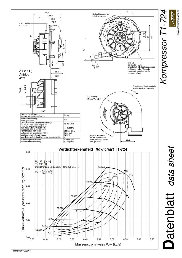
T1-724 Supercharger basic information, as well as OEM compressor wheel MAP. Be aware of the fact that the Germans are using mass flow in Kg/sec instead of Lbs/min. To convert from Kg to Lbs multiply the mass flow in this chart by 2,2044. Eks: 0,50 Kg/sec times 2,2044 is 1,102 Lbs/sec. Then multiply 1,102 Lbs with 60 sec, and you will get 66,12 Lbs/min.

This is the compressor wheel / impeller that comes with the ASA supercharger.
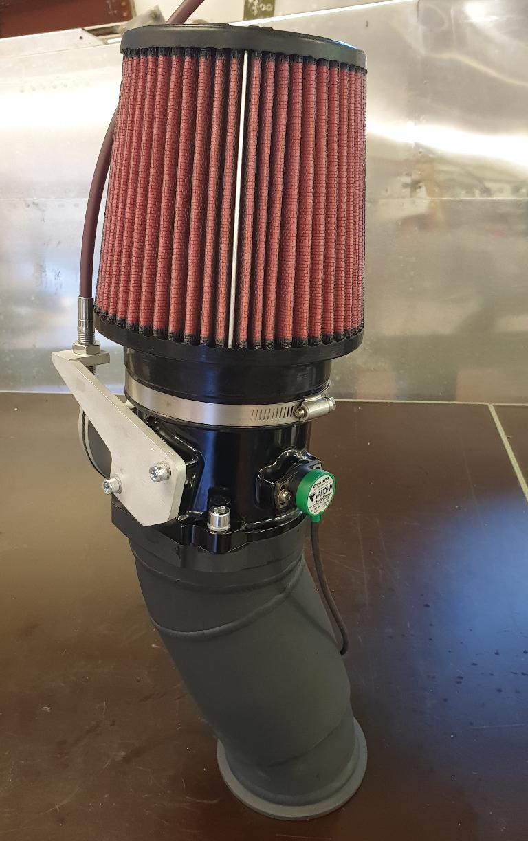
The problem solving 102 mm inlet manifold with throttle body and filter.
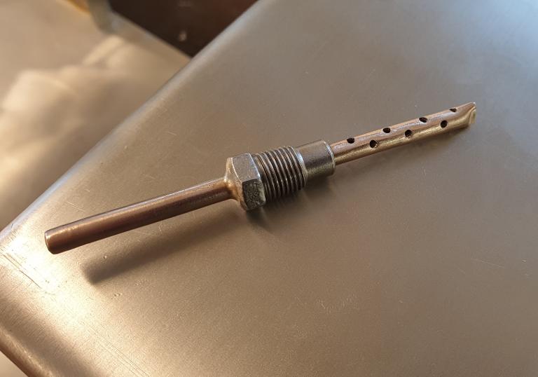
The homemade "tool" which we mount into the inlet manifold, just in front of the impeller, to be able to measure vacuum.
Issue two: Supercharger impeller
The ASA supercharger impeller could not deliver enough air to our V12, and the engine was therefore running out of steem too early. Halfway into the first phase of the test program, we understood that the supercharger could not deliver the amount of air that the engine needed. As you probably know already, the intake runner got most of our attention for a wihle, but since we were still lacking power, we had to start looking for other solutions elswhere in the system. The impeller caused extensive scrutiny. Mostly because the impeller actually was the only part left in the induction system that could be modified and thereby make a difference to the power output.
We started to look around for professional help to replace the existing impeller. From the start, I was thinking that we could just fit in a slightly bigger impeller from a modern tubocharger. As everybody knows, there is a myriad to choose from. Almost any size and shape is avaliable, either from an original equipment manufacturer, or from the aftermarket. I contacted ASA to ask for their help, but they refused to help us, based on the fact that there was nothing wrong with the original unit, which again was absolutely true! They also responded to us, saying that this could not be done in a responsible way, something we to a certain degree can understand, but refuse to accept! Arrogant you may say? Yes, it might be, but one can not tell an uneducated son of a Norwegian farmer that something can't be done, or is impossible! That is outright provoking! The Norwegian farmers always had to fend for themselves. That DNA is several thousand years old, and hardly ever modified. Ok, enough of the ranting!
Anyhow, a German turbocharger company was contacted. After a brief call and som explaining of the problem, we agreed on sending our supercharger unit to the company for them to do further investigation, but also the nessecary modification of the unit. Shortly after they replied that this type of work would be very complicated and problematic. This, despite the fact that the only type of work this company is doing, is customizing turbochargers! Suddenly I realized that it was the farmer's son, Mr. Wannabe, who was the problem.
Inspired by a compressor wheel
If nothing else, my creator was quite generous with me when ability for inspiration and creativity was handed out! I have to admit that I am very childish when it comes to take on new tasks, and to learn more about how things are working. Quite often, at least on Saturdays and Sundays, I am waking up in the middle of the night with new ideas on how to solve different challenges. Then it is just to get out of bed and get dressed for a new, and very often, inspiring day. Now, the time was come to customize the supercharger, and strangely enough, there wasn't a cloud on the horizon.
The KTS compressor wheel
Implementing a larger compressor wheel / impeller into a housing not designed for the impeller size, can be a critical operation. At least one needs to pay attention and be careful. First, I had to figure out how much material one could remove from the impeller housing without breaking through any of the walls. This was done just by looking at the housing and taking some rough measurments. It was obvious that there was no room for extensive changes. Then, before I started to remove any material, I had to find a compressor wheel that would fit to my preferences.
After a brief search on the World Wide Web for impellers, one is getting overwhelmed with results. After sorting out some of the possibilities, there was one company that caught my attention. The company was based in Kuala Lumpur, Malaysia, called KTS Turbo Billet. www.ktsturbobilletx.com After studying their web pages, it turned out that they had a portfolio of more than 6000 different part numbers of CNC maschined billet compressor wheels! The different compressor wheels / impellers were carefully organized into sizes and brands, which made it fairly easy to find what we were searching for. I found a billet copy of the Garret GTX4202R compressor wheel / impeller that i thought could be implemented without doing any harm to the original ASA housing. My good friend and parts distributor, Frode Komperød, the CEO of Sarpsborg Motor AS www.sarpsborgmotor.no contacted KTS Turbo Billet for guidance, before the final order was placed.
The beauty about a company as KTS Turbo Billet, is that they are willing to do any modification to any of their compressor wheels! Obviously, this will make customizing a turbo or a supercharger a lot easier for their customers. This is of course the strength and the very core of their business, and excactly what KTS did for us. KTS sent us a drawing which specified all the dimentions of the original Garret impeller. We then "customized" their drawing with our specific measurements and dimensions needed to be able to implement the Garret wheel into the ASA housing. To your information, we did not do any changes to the part of the compressor wheel that is in contact with the incoming or outgoing air. What we changed was the overall height of the impeller by removing material from the "superback" as they call it, or the rear side of the compressor wheel, but also from the top of the compressor wheel. A fixed 7 mm "left hand" nut was also incorporated in the top of the wheel, which makes this unit one part instead of two!
We had to order at least five units, and we had to wait twelve days for the order to reach Norway. And so we did, five units were ordered, and we waited for excactly twelve days. Frode Komperød called me on day twelve, with the message that the parts had arrived. So little fuzz, no misunderstandings, no excuses, extremely high quality parts, and delivered on time. What can I say, other than that I am very impressed and satisfied with KTS Turbo Billet. Mike Tho, and all of you at the KTS Turbo Billet, thank you!
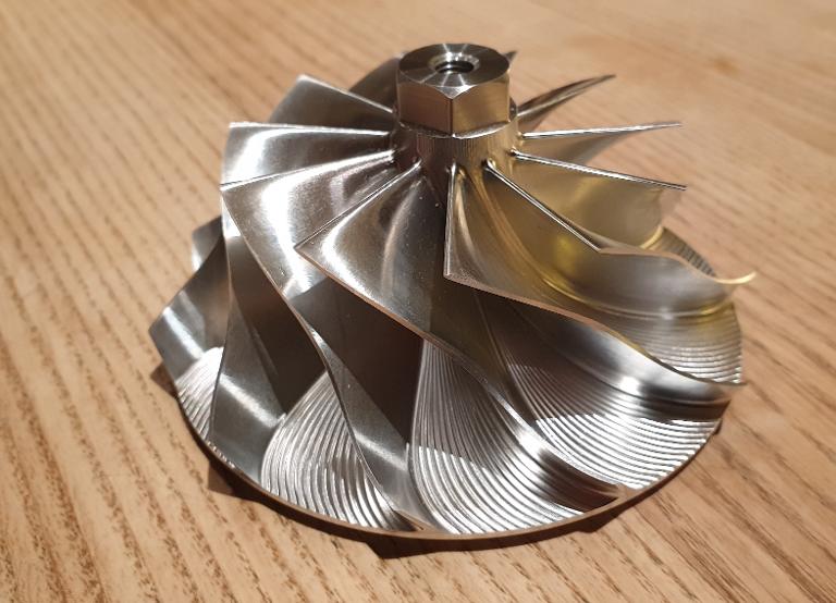
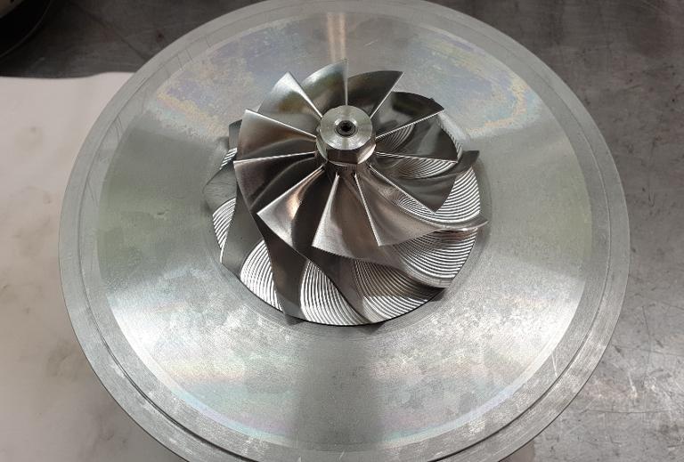
The billet GTX-4202R compressor wheel, pictured here, is currently what we are using in the ASA housing. It is designed and manufactured by KTS Turbo Billet. www.ktsturbobilletx.com This is is a CNC machined part! We are really stunned with the work and quality of this part.
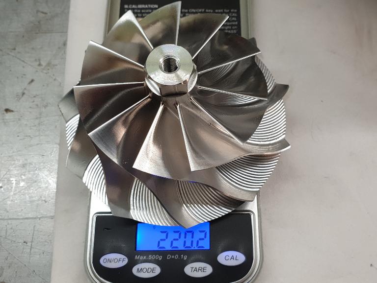
The KTS compressor wheel is weighing in at 220,2 Grams or 7,77 Ounces which is 24,7 Grams or 0,87 Ounces less than the OEM compressor wheel.
The final machining
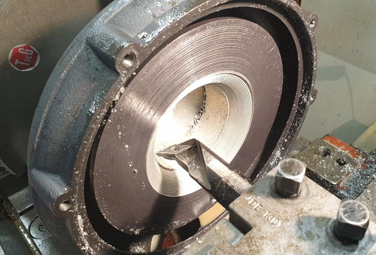
I had never machined a turbo or supercharger impeller housing before, so I was not quite sure how to "attack" the situation. Anyhow, I started out machinig the rear plate so that I could get the impeller lowered into a perfect position. After the new impeller was mounted onto the threaded shaft and tightend to spesification, I installed the "rear plate" with the impeller into one of our lathe's, so that I could measure the contour of the new impeller. I used the tip of a cutting tool to just barly touch the impeller blade in the Z axis, for every step of 0,5 mm or 0,020 increments in the Y axis. By doing so, I obtained a numerical "picture" on how the contour of the impeller should look on a pice of paper. By adding 0,5 mm or 0,020 Inch to the measurments, I had established impeller to wall clereance.
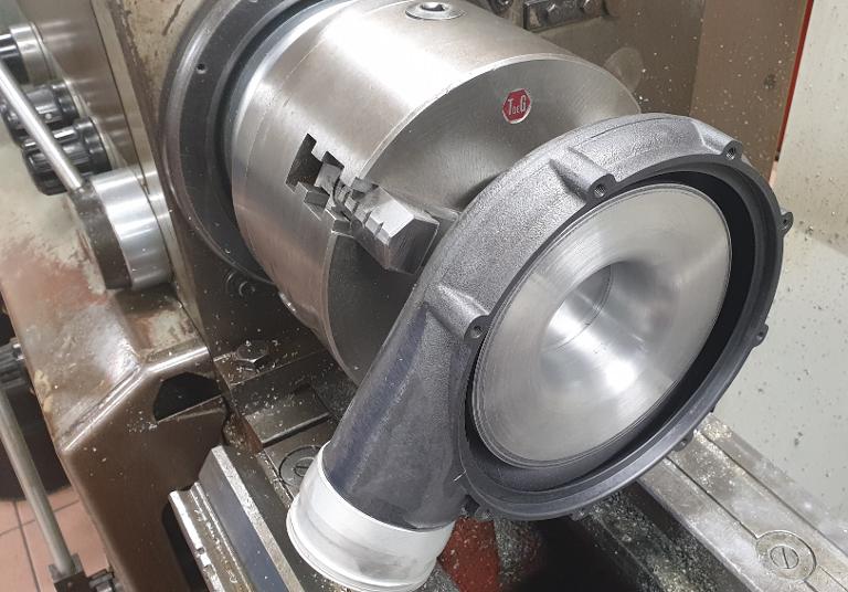
I made a fixture for the ASA compressor wheel housing, also called the volute. This so i could make an excact and stirdy attachment to the lathe's chuck. I dialed in the center of the housing to within 0,010 mm or 0,0004 Inch and started, with caution, to follow my numerical "chart". It was actually nothing to be worried about, and a lot easier than I first expected it to be. I used a regular sanding paper to carefully grind away all of the radial groves after the cutting tool. I finished with a 3M cloth to get a nice even surface. When there were no traces left after the cutting tool, I considered my work done.
Assembling the hybrid
In the pictures to the right, you might grasp the idea of how this process was done. The author of these pages thinks words do a lousy job explaining technique and mechanics! The same author thinks that pictures do a better job at it. Anyhow, there is little more than common sense to this process. Inspiration serves as a "fuel" to power you through something that might be a bit scary in the first place, and is a welcome ingredience. At least it is for me. The willingness to take the risk of ruining some parts will also come in handy! People have done this before me, and this was just my approach to solve this task.
I carefully lowered the newley machined impeller housing over the KTS billet impeller, which was now secured and tightend down to specifications. It was a welcome sight to see that there was no interference between the two parts. I measured the housing or volute to impeller tip clereance, which was 0,25 mm or 0,001 Inch, as I was hoping for. Bellieve it or not, It fit perfectly.
Testing for gains
The number 650 in the name of the engine, ASE-650 Saga, dictates what we are expecting as a theoretical power output. The first dyno results we got after we had roughly dialed in the basic fuel and ignition settings, was, 614 Hp @ 5000 RPM and 646 Lb-ft / 875,5 Nm @ 4900 RPM with 22,5 Psi / 1,58 Bar of maximum boost. Aerosport Engineering has had a fairly uniqe opportunity to arrange a session in the ARP dyno cell on a short notice. Since we were troubled with air restrictions in the intake manifold, we had several dyno test sessions in which to figure out these problems. The final dyno session showed that we had reached and surpassed our goals. The improvements that we had done to the intake air manifold and the supercharger gave us a gain of 61 Hp and 63 Lb-ft of torque. Then it looks like this: 675 Hp @5000 RPM with 23,5 Psi / 1,65 Bar of boost pressure. And, 718 Lb-ft / 976 Nm of torque @ 4800 RPM with 22,5 Psi / 1,58 Bar of boost pressure.
Compressor wheel speed
If you are curious about the speed of the compressor wheel or the impeller, then this is it: Maximum take of and operating RPM is set to no more than 5000. The step up ratio of planetary gear set is 1:15. The main, and driving pulley on the cranckshaft is 205 mm or 8,07 Inch, and the driven pulley on the supercharger is 155 mm or 6,1 Inch in diameter. 5000 RPM X 15 X 205 divided by 155 is: 99193 RPM.
Test phase two
Because of a new and wider intake manifold, throttle body and filter, we also reduced the vacuum in front of the superchager to alomost nothing. So far we are done in the dyno cell, and we are now preparing for test phase two in the early spring of 2021. Then it is time to go outside, with PSRU and a propeller and get elevated! By the way, it amazes me that you took your time to read this pretty dry and boring stuff all the way to the end! Thank you! Stay tuned.
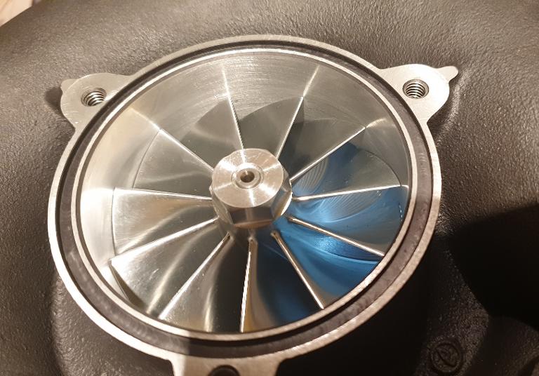
The KTS impeller is "tried out" for the first time in the freshly machined ASA compressor housing. Wall to impeller clereances is 0,25 mm or 0,01 Inch.
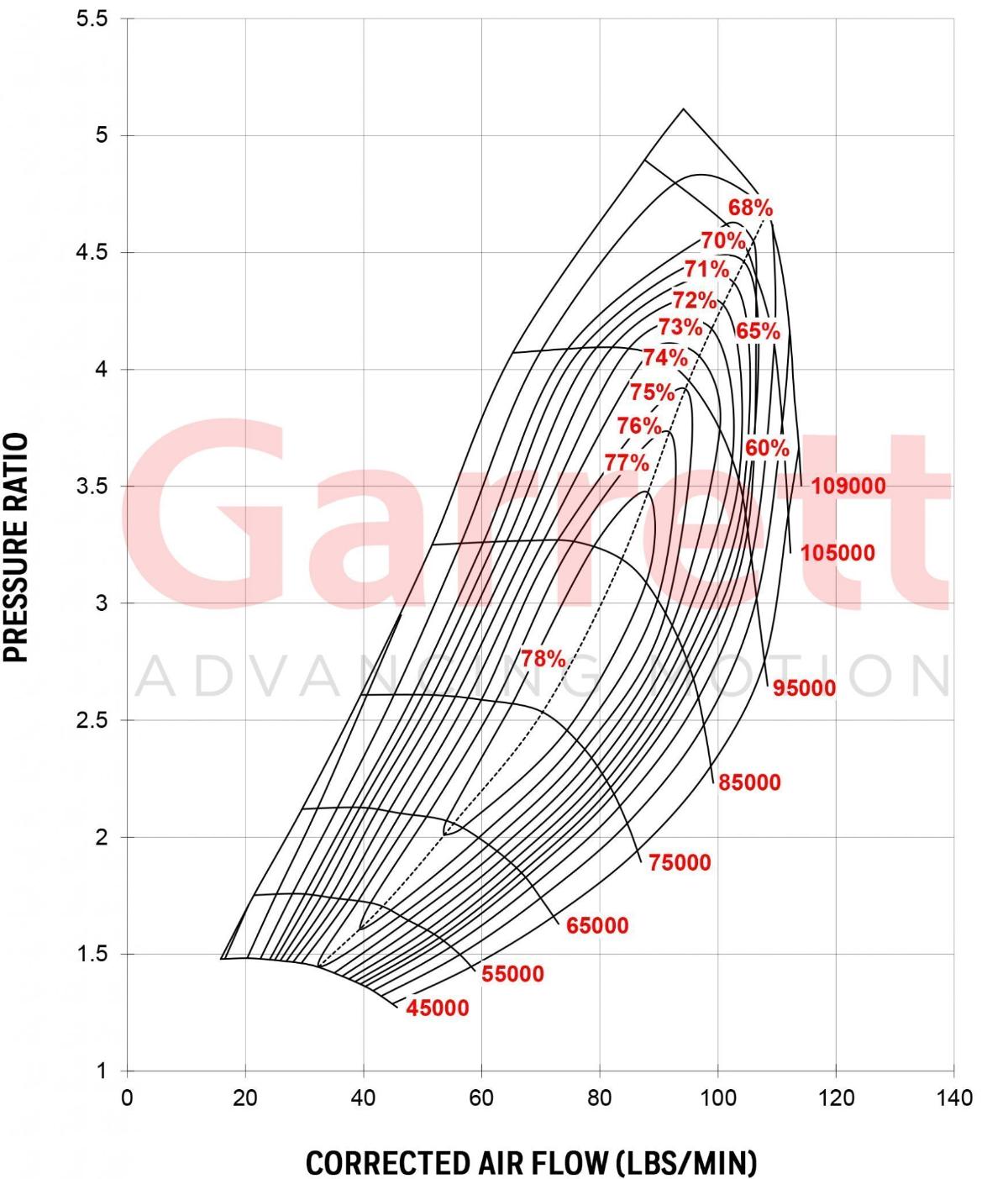
Garret GTX-4202R Compressor wheel MAP

With a comparison of the two, one can see that the KTS impellers overall diameter is lager than the OEM impeller. What is even more interesting, is the much thinner wall thickness of the blades in the KTS compressor wheel.
The "rear plate" has been adjusted so that the supercharger wheel is resting at the right height.
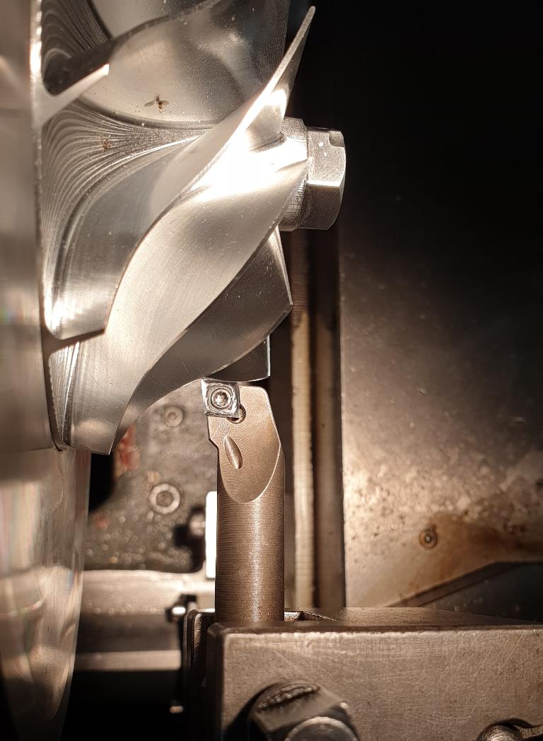
Measuring the new KTS compressor wheel in increments of 0,5 mm at a time in the Y axis, to establish a "chart" in both the X and the Y axis. This so that we would be able to machine a precise contour for the new impeller in the OEM housing.
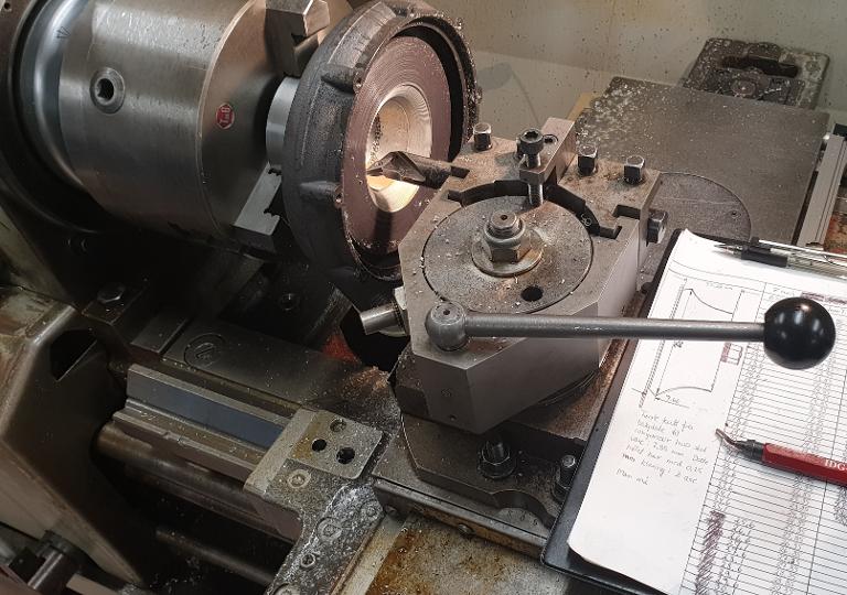
Our old friend, the Russian Koneisto lathe, lends out a helping hand. The very high technology Ole-CAD files to the right gets loaded into the machinery manually. A small portion of the Norwegian humor can't do any harm.
The radial groves from the cutting tool you se in this picture was sanded down until they dissapeared. Stone-Age engineering one may say, but the result came out close to perfect. The exercice itself is pure fun, and quite educating. That's two of the reasons why we are here, right?
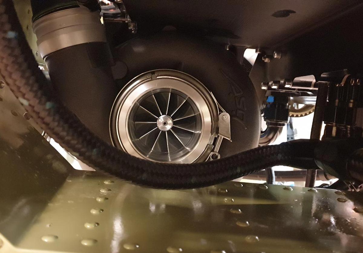
In this picture the supercharger with the new compressor wheel is on its way back into the engine and soon ready for another "battle" in the test cell.
We went from a 73,5 mm to a 76 mm opening. It does not sound like a lot, but together with the fact that the new KTS impeller is more modern and efficient, it makes a noticeable difference.