
PSRU
Every experimental aircraft builder of the more advanced category, where a Propeller Speed Reduction Unit is required, will most likely end up with more questions than answers. Or in other words, as a responsible pilot of your aircraft, you should have questions, and also be rather critical to the many different vendors who are offering their more or less thoroughly prepared systems. Due to the fact that gears have been our main occupation in a different but still successful business since 1988, www.rats.no we have had a very keen eye on the different products on the market.
So, how difficult is it to make a reduction unit through two, or at the most, three gears, when an idler gear is incorporated in order to change direction? We have concluded that it must be quite difficult, after having investigated the numerous accidents where a PSRU is involved.
In 2017 Aerosport Engineering AS bought the intelectual properties, drawings, tools and equipment, together with the already manufactured parts for the Mark 15 Propeller Speed Reduction Unit from Burhoe Machine Works. We have since then been working with focus on how to further develop and preserve an already well engineered and excellent product made by Jack Kane, the CEO of EPI-Inc.
When we use the term "further development" this means that we are working on adapting the PSRU to match new engines and Powerplants that new clients would need. In that regard, we are already looking into making conversions where Diesel Engine Power will be one of the new parts in an already busy propulsion package.
Aerosport Engineering has not made any changes to any internal design or components. We have made several new bellhousings in order to mount the PSRU directly onto the engine without any other adapter. We have also incorporated a secondary alternator into the bellhousing for electrical redundancy. In addition, as mentioned under the chapter “Lubrication and oil system”, we are using one of the engines scavenge pumps to drain the excessive oil from the PSRU. Also, we have made a complete "stand alone" oil and lubrication system with a brand new Auto Verdi designed two stage pump, whith an adjustable regulated Pressure Stage and a Scavenge Stage for draining oil out of the PSRU. This system includes a designated oil cooler, an oil filter adapter, Dry Sump Tank, and necessary plumbing.
The Mark 15 PSRU can handle loads of 1500 Hp, and the weight for one of the Single Mesh units can be as low as 39 kg / 85 lbs. The upper image to the right shows a Single Mesh unit installed on one of our ASE-650 Saga V12 engines. The weight will necessarily vary for various reasons, such as gear ratio and width of the gears, inertia ring weight, oilpumps and oilcoolers if required to make a safe propulsion system.
The many different gear ratios avaliable will make it easier to optimize propulsion packages to fit perfectly with regards to aircraft properties, engine power and propeller size. The Mark 15 Dual Mesh unit, pictured to the right, is designed with an idler gear to have your propeller turn the same way as your powerplant. In other words, this means that you are free to choose a PSRU for any propeller direction, no matter which way your engine is turning.
 (1).jpg?v=1791891851167)
 (1).jpg?v=1791892371255)

EPI Inc.
Anyhow, we have found one vendor who has convinced us by their thorough and well founded solutions. The EPI Inc. is the only company to follow up their offer with a thorough explanation about how gears have been made through history, with examples from companies like Allison, Rolls Royce and Pratt & Whitney. Furthermore, you will find on their web pages, www.epi-eng.com, more than 130 pages with technical information which has been used by engineers and designers for many decades.
EPI also offers detailed information on torsional vibrations, fretting resonances and other dangerous side effects that you may experience when operating gears or other mechanical devices. Jack Kane, the founder and CEO of EPI Inc. also explains how to eliminate these problems, and designs PSRUs which incorporate both the idea of how to deal with the above mentioned effects, the technology and hardware to eliminate the same problems, and make your aircraft safer.
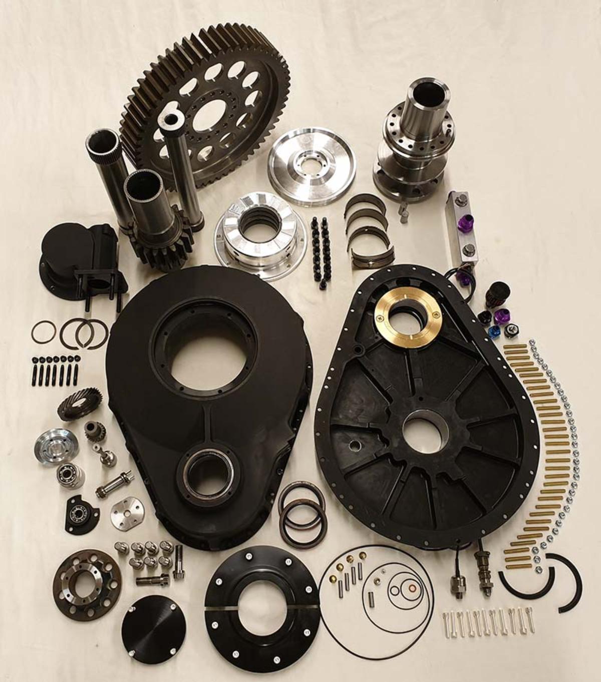
This is a picture of most of the parts involved to complete a Mark 15 PSRU. This is a single mesh unit, which means that the reduction unit contains only two gears, input shaft gear and propeller shaft gear, but no idler gear to change direction. In other words, this will turn the propeller in the opposite direction of engine rotation.
Torsional Isolation.
The most important part of this page!
Dear reader, like it or not, you will have to consume a few graphs and physics before we continue with more information regarding this splendid product. We need to look at some of the physics “hidden” in a vibratory system, like the one in the Intermittent / Internal Combustion engine. We assume that some readers would like to know more about the unhealthy problems arising in a running propulsion system driven by a piston engine, but also if there is a cure for any of these problems.
Let’s take a look at the events happening in a propulsion system driven by any Intermittent / Internal Combustion engine. And yes, this time we need to look at some graphs and numbers. We think you should give yourself the time to consume some of this. It is enlightening and actually quite interesting when one starts to understand the concept.
And, to your information, this article is written by the designer of the Mark 15 PSRU, Mr. Jack Kane.
The concept of Frequency Ratio
The graph you see below is a plot of transmissibility vs frequency ratio.

A Tuning Fork
When you strike a tuning fork against something hard, it vibrates at a fixed frequency. That frequency is the Resonant Frequency of that particular tuning fork. Suppose you struck a tuning fork that is "A4" (the next "A" key above "middle C" on a piano keyboard). That frequency is 440 cycles per second or 440 Hertz, Hz. That is the "resonant frequency " of that tuning fork. Different forks will have different Resonant Frequency’s based on the dimensions of the legs and on the stiffness of the material.
Resonant Frequency
The Resonant Frequency of a system is important, because a vibrating system behaves differently depending on how often it is "struck"!
The torque pulses that a piston engine produces act as an "excitation" (like, repeated strikes on the tuning fork) on whatever the engine is driving.
The frequency of that "excitation ", in pulses per second, is: Engine RPM divided by 60 multiplied with the number of cylinders divided by 2.The RPM is divided by 60 because we need pulses per second, and the number of cylinders is divided by two because each cylinder in a 4-stroke piston engine produces a torque pulse every second revolution.
So, for an 8-cylinder, and mind you, an even-fire engine operating at 4000 rpm, the excitation frequency or pulse rate is (4000 divided by 60) multiplied by (8 divided by 2) = 266.67 Hz.
For a 12-cylinder, even-fire engine operating at 4000 rpm, the excitation frequency is (4000 divided by 60) multiplied by (12 divided by 2) = 400 Hz.
Now, let’s suppose we attach a gearbox and propeller to an even-fire V8. And let's say that the Resonant Frequency of that system is 40 Hz. Then at 4000 engine rpm, the engine will be applying a pulse rate of 266.67 Hz to the gearbox/propeller system. That pulse rate of 266.67 Hz is 6.66 times the Resonant Frequency (40 Hz), or a Frequency Ratio of 6.66 (266.67 divided by 40).
Now, if we replace the V8 with an even-fire V12 that has the same effective mass moment of inertia that the previous V8 had, then the system Resonant Frequency will be the same (40 Hz) but the engine will be applying a pulse rate (excitation) of 400 Hz to the gearbox/propeller system, which gives a Frequency Ratio of 10. (A Pulse Rate of 400 Hz divided by the Resonant Frequency of 40 Hz equals to a Frequency Ratio of 10)
So, if you want to examine the behavior of different systems at different excitations, it is useful to do the comparisons with respect to the Resonant Frequency.
Some Examples
Let’s say we are interested in 880 Hz with respect to a Resonant Frequency of 440 Hz, that is a Frequency Ratio of 2.0 (880 divided by 440 equals 2).
Or, if we are interested in 220 Hz with respect to a Resonant Frequency of 440 Hz, that is a Frequency Ratio of 0.5 (220 divided by 440 equals 0,5)
And, 1000 Hz is a Frequency Ratio of 2.273 (1000 divided by 440 equals 2,273).
So, suppose we wanted to investigate the response of a system that has a Resonant Frequency of 500 Hz to an applied input of 1000 Hz. That is Frequency Ratio of 2.0 (1000 divided by 500 equals 2). The reason for using Frequency Ratio is that the response of any system at a Frequency Ratio of 2.0 will be the same with respect to Resonant Frequency. By using the Frequency Ratio factor, one can represent the response of a system to a given input as a function of that system's Resonant Frequency, rather than plotting different curves for each different system.
Transmissibility
Transmissibility (can also be thought of as "force ratio") is the measurement of the amplification - or reduction - of the pulse amplitude that a driven system experiences with respect to the amplitude of the pulses that the engine applies to the system.
The typical pulse output of a V8 at the crankshaft flange is shown in the figure below. That curve shows that the peak amplitude of the instantaneous output torque curve is roughly twice the value of the "mean torque " (what the Dyno measures). So, for a mean torque of 500 lb-ft, there would be four spikes of 1000 lb-ft per revolution. If the transmissibility value was 1.0, then those spikes of 1000 lb-ft would be applied to the driven load.

If we have an engine operating at 4200 rpm, driving a system with a Resonant Frequency of 200 Hz, then at 4200 engine rpm, the engine would be applying 280 torque pulses per second (Hz), so the system would be operating at a Frequency Ratio of 280 Hz divided by 400 equals 0.700.
If you look at the graph above, you can see that at a Frequency Ratio of 0.70 for a system with ZERO DAMPING (blue curve), the transmissibility value is approximately 2.0.
That means that the spikes applied to the driven load will be multiplied by 2.0, so the driven load will see four torque spikes of 2000 lb-ft four/4 times per revolution.
If, however, the system Resonant Frequency could be reduced to 40 Hz, then at 4200 rpm, the system is operating at a Frequency Ratio of (280 Hz divided by 40 Hz equals) 7.0, and at that Frequency Ratio, the transmissibility is approximately 0.021, so the torque spikes seen by the driven load are REDUCED to 0.021, or 42 lb-ft.
Thus, the driven load will see (for 500 lb-ft mean torque) a fluctuation of +/- 42 lb-ft - from 458 lb-ft (500-42) to 542 (500+42) lb ft, four times per revolution.
Critical Damping
Critical Damping is the amount of damping that will reduce the amplitude of a single excursion of a system to its equilibrium position without any oscillations or overshooting.
The Damping Ratio ( â ) is the ratio of the value of damping in the system to the value of critical damping for that system.
Zero is the target; 0.25 is about the very maximum one would allow. As one can see from those curves, more damping reduces the AMPLIFICATION below the crossover Frequency Ratio (which is 1.414 multiplied with Resonant Frequency) but above crossover, damping reduces the reduction in transmissibility that we want.
ZERO DAMPING is quite obvious. And ZERO DAMPING is the target in the system solutions that we build – (see the blue curve).
And that’s it! Thank you for taking your time to read this all the way to the end.
There are two versions of the Mark 15 PSRU

Single Mesh
Click on either of these two images to learn more about the two different versions of the Mark 15 PSRU, Single Mesh & Dual Mesh.

Dual Mesh
Bellhousing's or PSRU Adaptors
The engine to gearbox adapter is a very essential part in order to be able to mount the PSRU to the engine. Normally these units serve several missions. The first and the most obvious mission is to be able to mount the PSRU to the engine, since the engine and the PSRU do not have the ability to share the same bolting pattern, and also to be able to include the very important vibration absorption technology, which you will learn more about in this article. The second feature is that it has it has mounting flanges machined on both sides, so that engine/gearbox vibration mounts can be attached.
.jpg?v=1791976413739)
Bellhousing ASE-650 Saga V12
 (1) (1) (1) (1).jpg?v=1791976687267)
Bellhousing GM-LS/LT
 (1) (1) (1).jpg?v=1791976860419)
Bellhousing Chrysler 426 Hemi
.jpg?v=1791977743983)
Redundancy Alternator
The third feature, and maybe not so commonly seen, is that we have, with the help of Jack Kane at EPI Inc, been able to incorporate a second alternator attached to the bellhousing, using it's own set of pulleys and a multi rib belt. This particular belt does not have any other mission but driving the alternator. For your information, there is another alternator mounted in the other end of the engine, where the multi rib belt runs both the alternator and the water pump. For redundancy reasons, we found it important to drive the alternators from two different sources. For example, if one of the multi rib belts fail, we are loosing only one alternator.
In the pictures above you can see the “cut out hole” for the governor on the side of the Bellhousing. You may also see that the Bellhousings has some convenient spots where you can mount other features. The complete Bellhousing, or adapter unit, as some like to call it, is machined out from a block of 7075- T6 aluminum alloy. This high grade aluminum alloy chosen for this component, and actually all of the aluminium components in our PSRUs, makes it very sturdy, this in addition to the average wall thickness of 8 mm/0,315 Inch! The weight of an average Bellhousing is only 10 Kg / 22 Lb.
PSRU features
We would like to show you some of the features of the Mark 15 PSRU, and that means we have to go a little deeper in details.
First of all, EPI / Aerosport Engineering gearboxes use hydrodynamic fluid-film bearings (just like the crankshaft bearings in your engine) in both ends for the propeller shaft. The same design is used in both ends of the input gear shaft as well. These bearings have far greater capacity than rolling-element bearings of the same size, and are much lighter and physically smaller than the rolling element bearings needed to carry the large loads required. In addition, the thrust-handling capacity of ball bearings (which some PSRU's use for their propshaft) is extremely limited.
The vertical offset between the crankshaft centerline and the prop centerline is 200.66 mm or 7.90 inches.

 (1) (1) (1).jpg?v=1791973362403)

The available ratios
The available ratios are: 1.724, 1.821, 1.926, 2.038, 2.160, 2.292, 2.435, 2.478, 2.591, 2.762, 2.950, and 3.158.
The Mark 15 PSRU can be manufactured in two different versions. With either direction of prop rotation with either direction of engine rotation. This can be done by adding an idler gear to the unit. The gear housings, front and rear, will obviously be different to be able to incorporate another gear to change direction of the propeller shaft. This is now what we call a two mesh gear box. Illustration picture is from a Single Mesh Unit.
The input torque capacity exceeds 1600 lb-ft. (depending on the required safety-margin).
The propeller thrust capacity (all configurations) is 3000 lbs. in either direction (pusher or tractor applications).

 (1).jpg?v=1791968093163)
SAE ARP-880
 (2).jpeg?v=1791968238556) SAE ARP-502
There are two avaliable propeller flanges, where one of them conforms to popuar SAE ARP-880, which is the 8-bolt, 2-dowel configuration used on the P&W PT-6 and Garrett TPE-331 turbine engines, and most Continental GTSIO-520 engines.
The other flange, also very common, is the SAE ARP-502, which has a 6-bolt, 2-dowel configuration.
The minimum length from the rear of the engine to the attacment surface on the propeller flange is 14 inches. If necessary, the propeller shaft can be extended in all increments up to 2 inches to move the propeller further away from the engine to assist with specific cowling issues.
The important Governor integration
The integrated controllable propeller system is the common single-acting hydraulic configuration (Hartzell, McCauley, AeroComposite, MT, Hoffmann, etc.) found in most piston-engined aircraft.
The propeller governor drive is integrated into the gearbox and provides an AND-20010 governor mounting pad, vibration-isolated gear-drive, and internal propeller control plumbing.
The Mark-15 includes provisions for a reversing prop and the PT-6-style Beta-Feedback mechanism for the control of a reversing propeller.
The Governor presented in the pictures is an MT unit with the Beta feedback system. As you can see, the Governor has two integrated solenoids, where one of the solenoids controlls Beta Mode, or reverse propeller thrust mode, and where the second solenoid works as a "flat pitch stop" device to prevent the propeller to go into Feathered Position after stopping the engine. If the solenoid is not engaged, the propeller goes to feathered position when the engine are shut down, or stops unintentionaly.
.jpg?v=1791978859347)
 (1) (1) (1).jpg?v=1792042648245)
Governor Drive Mechanism
In the picture below, you can see the special designed parts necessary to drive the Governor. The Governor Drive gear (the larger one in the back) is driven by the rear end of the Propeller Shaft (not pictured) which drives the Driven Gear (the smaller one). You may also spot the cleverly designed Torsionally Isolated drive shaft with the internal spline facing upwards. The Driven Gear is attached to this shaft, which again drives the Governor. All of this parts are assembled together inside the fairly small and black anodized Governor Housing and mounted neatly and safely inside the Bellhousing with only the Governor Mounting Pad visible from the outside.
 (1).jpg?v=1791978946738)
PSRU Weight
The lightest version (single-mesh) weighs just short of 40 kg / 88 Lbs, with the governor and Bellhousing. The Bellhousing itself is about 10 kg/22 Lb depending on the engine. The weight of the PSRU varies with ratio, torque capacity and direction of prop rotation, which indicates that the Single Mesh unit weighs less than the Dual Mesh unit.
In addition, to be able to fit our PSRU onto our ASE-650 Saga (BMW M73-B54 block), the Mark-15 has provisions to fit many popular and even unpopular engines: Smallblock and Bigblock Chevrolet, GM-LS / LT, Ford Windsor, Chrysler Hemi, Falconer V12, and many more. This all depends on what our clients are suggesting. We are also looking at implementinng our PSRU's for Diesel Propulsion in the near future.
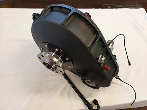
The picures below can be a bit misleading. This since there are several ways of implementing a gear-box. Some installations do not need a separate lubrication system, while others do. The weight scale in the right picture shows a total weight of 61,6 Kg / 136 Lbs. Included in the weight is a complete separate lubrication system that one of our clients need for their propulsion system. You may also spot the Flywheel or Inertia Ring as we like to call it, crankshaft hub, bolts, sensores, wiring harness, hoses, fittings, adapters, and 5 Lt / Qts of oil for the system. All of these items add weight, but are still necessities in a reliable stand alone lubricating system.
.jpg?v=1791980787675)
.jpg?v=1791981329668)
Lubrication
The Mark-15 PSRU can use the engine's lubrication system and by that, the engine's oil for lubrication, cooling and propeller control, so it requires no additional heat exchangers, which helps to reduce cooling drag. This is the most common lubrication method.
In some cases, the situation is different. We have clients that have chosen powerplants where the engine cannot be the source for lubrication due to limitations in oil volume and pressure. We have seen several modern engines where pressure is electronically controlled, often due to emission requirements, where the engine manufacturer is forced by Governmental rules to produce less emissions regardless of what consequenses it may lead to. As an excample of this, the 2014 and up Chevrolet V8 LT platform restricts the maximum oil pressure to no more than 40 Psi! The idea is that the pump will turn easier with less pressure to produce, and by that reducing emissions. The emission gain is insignificant, but that is evidentely more important than protecting the engine itself. Sometimes, and more often than ever, I'm puzzled by many choices done by us humans.
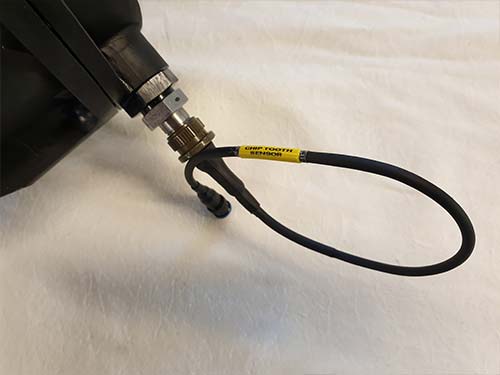
The Mark-15 also contains several gearbox "health-monitoring" features, including a chip detector placed at the bottom of the gear box casing, two temperature sensors (for incoming and exiting oil) and an oil pressure sensor location. The temperature sensor has a 1/8 NPT thread and can be placed at two different locations on the unit.


PSRU Assembly
Here is a picture of parts for several PSRU's which are ready for assembly.

Aerosport PSRU Testing Program
Why testing?
Testing a Propeller Speed Reduction Unit extends beyond a general quality check. One of the obvious reasons for testing gearboxes or any other mechanical device, is to find out if something is NOT right, to reveal smaller problems and errors before they become a REAL problem. Most errors are human made, be it errors in a smal assembly line like ours, errors made during the manufacturing of the part itself, or when choosing the quality of the material used for manufacturing. And what about the complex hardening process? How did that go?
When this is said, let us make one thing VERY clear! We are really trusting all our valuable vendors to the outmost! All of them, without exception, are ISO Certified. They all deliver Material Certificates, or ANY certification we demand, this so we can gain controll of our production. We also do random material quality checks in a third party laboratory here in Norway, just to confirm that we are getting the Material Quality and the Hardening Specification we ordered.
However, even if all precautions are followed, unfourtenate circumstances may occur! Of course you have heard the expression, the DEVIL is in the details. Have you ever thought of why that saying was invented in the first place?
There are many places in such production where things can go wrong and where the ultimate consequense of such failure can have a fatal outcome. This is an unberable thought to us, and the reason why we are testing our products. Tolerances of any part can be measured before any assembly is started, but that is only half the story.
How do we test, and what do we look for?
First of all, we are building our own test equipment. We have built several Test Stands, and we will most likely build more of them in the future. Some of the assignments we take up on are very different, and cannot be tested in a "traditional" way, which forces us to make a new Test Rig only for a very particular Powerplant where the architechture and control system are very specialized.
The Test Rig in the picture to the right is made for testing PSRUs only. Not engines or Powerplants. With this Rig we can test both Single Mesh & Dual Mesh units. The engine used in this Rig is the well known Chevrolet 6,0 Lt LQ8 V8. This must be one of the best engines ever produced, not the most powerful, (325 Hp) but extremely reliable. This pore guy has been abused to the extreeme over long periodes of time without showing any signs of giving up.
When we do the first "Start-Up" of a newly assembled PSRU the first thing we are waiting for is the obvious oil pressure. Now, and to your information, all of the bearings, trust washers and rotating parts inside the PSRUs are well lubricated befor assembly. This so all of the components can rotate safely for a while without the needed oil pressure. Remember, the oil pump must fill the Propeller Shaft, but also the Propeller Hub, and all other smaller or larger cavities inside the PSRU, before the designated pressure can be reached. We like to run the engine at fast idle, like 1200 to 1500 RPM. When oil has reached all components and pressure rises, the next thing happening is that some propellers are changing pitch, all depending on how they are built from the factory. E.g. pressure to increase or pressure to decrease pitch. As you can see, the MT propeller in the picture to the right is in a feathered position. This particular unit needs pressure to decrease pitch, where the oil pressure will force the propeller blades to go to fine pitch after Start-Up. During the test run we constantly monitor main oil pressure, oil volume going through the unit pr/minute, oil temperatur of the incoming oil, but also, and more imoportantly, the temperature for the outgoing oil. And recently we have been monitoring Governor Pressure as well. It is actually quite interesting to see how much pressure needed to be able to vary propeller pitch. As the reader of these web pages, you can also watch videos where the Governor pressure varies when the Governor is working the propeller blades.
After some light RPM's and loads of the engine and gearbox, just so we get some heat buildt up in the units, we are ready to start loading the gears in the PSRU. We normally run every PSRU between one and two hours. During the test period, the average load will vary between 65 and 100%. We are varying propeller pitch many times during the test-run, this to load propeller trust bearings, among other functions. If the client has ordered a Reverse Thrust propeller with the associated Beta Governor system like the one in the picture, we obviously test this sytem as well.
Now, are any of you concerned about how the massive thrust forces generated by the propeller is taken care of? You should be, and if you are, then we suspect that you have been witnessing some "scary stuff engineering" in somone's homebuilder garage. First of all, the two propeller shaft Thrust Surfaces, (one on each side) integrated in the part we name, the Main Propeller Shaft Housing, are VERY generous. And secondly, oil pressure is forced between the thrust surfaces and the propeller shaft Thrust Flanges, and by that keeps the Propeller Shaft well balanced in center of the Main Propeller Shaft Bearing Housing. During the last period of the test we run our equipment on 100% full throttle. Our goal is to make sure the gears are broken in, and that any abraded particles, if any, are captured by the oil and transported to the filter. We are quite meticulous, which means that every filter is opened for inspection of the filter mesh.
.jpg?v=1791983807042)
.jpg?v=1792225469673)
Hardcore Mark 15 PSRU Test Video
In the aproximately eight minute Video below you can watch us test a clients Mark 15 PSRU. This Video Clip is an excerpt from a Long-Term test going over 60 hours. In connection with a Certification process with Bureau Veritas, we had to test this particular PSRU for an endurance of minimum 60 hours. We have made a total of eight similar units for the same client, which made the total time passing 80 hours. This PSRU is equipped with a selfcontaining or Stand-Alone oil and lubrication system which we made spesifically for this client. We are not sure if the term ENJOY is the right one to use regarding this video, but still, we hope that you like som of it!
Yours sincerely, Ole Ringstad & Cecilie B. Bjørnebye.